6
5
MHT 10120 L M
Series
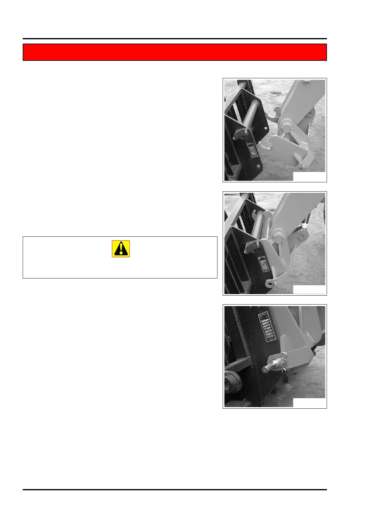
ENGAGING THE ACCESSORY
- Check that the accessory is in a position which simplifies connection
of the snap coupling. If it is badly positioned, take the necessary
precautions to move it in the conditions of maximum safety.
- Check that the locking pin is engaged in the support provided on the
frame.
- Position the lift-truck with the boom lowered squarely in front of and
parallel to the accessory and tilt the snap coupling forward (Fig. A).
- Bring the snap coupling into position below the accessory’s connec-
tion pipe, raise the boom slightly and tilt the connection back to posi-
tion the accessory (Fig. B).
- Raise the accessory off the ground for easier engagement.
MANUAL LOCKING AND CONNECTION OF THE ACCESSORY
- Take the locking pin on the support and fix the accessory (Fig. C).
Do not forget to fit the split-pin.
- Switch off the engine.
- Eliminate the accessory hydraulic circuit pressure using the optional
control (refer to the “controls” pages of the use and maintenance
manual).
- Connect the snap couplings, following the description of the hydraulic
movements of the accessory.
Keep the snap couplings clean and protect the unused orifices with
the caps provided.
REMOVING (AND PUTTING DOWN) THE ACCESSORY
- Proceed in reverse direction to the ENGAGING THE ACCESSORY
procedure, taking care to place it in a safe position on firm, flat
ground.
ACCESSORY WITH HYDRAULIC SYSTEM AND MANUAL LOCKING (OPTIONAL)
ACCESSORY WITH HYDRAULIC SYSTEM AND MANUAL LOCKING (OPTIONAL)
Fig. A
Fig. B
Fig. C
 Loading...