Manitowoc Published 07-23-15, Control # 078-03 4-43
31000 LUFFING JIB OPERATOR MANUAL SET-UP AND INSTALLATION
44
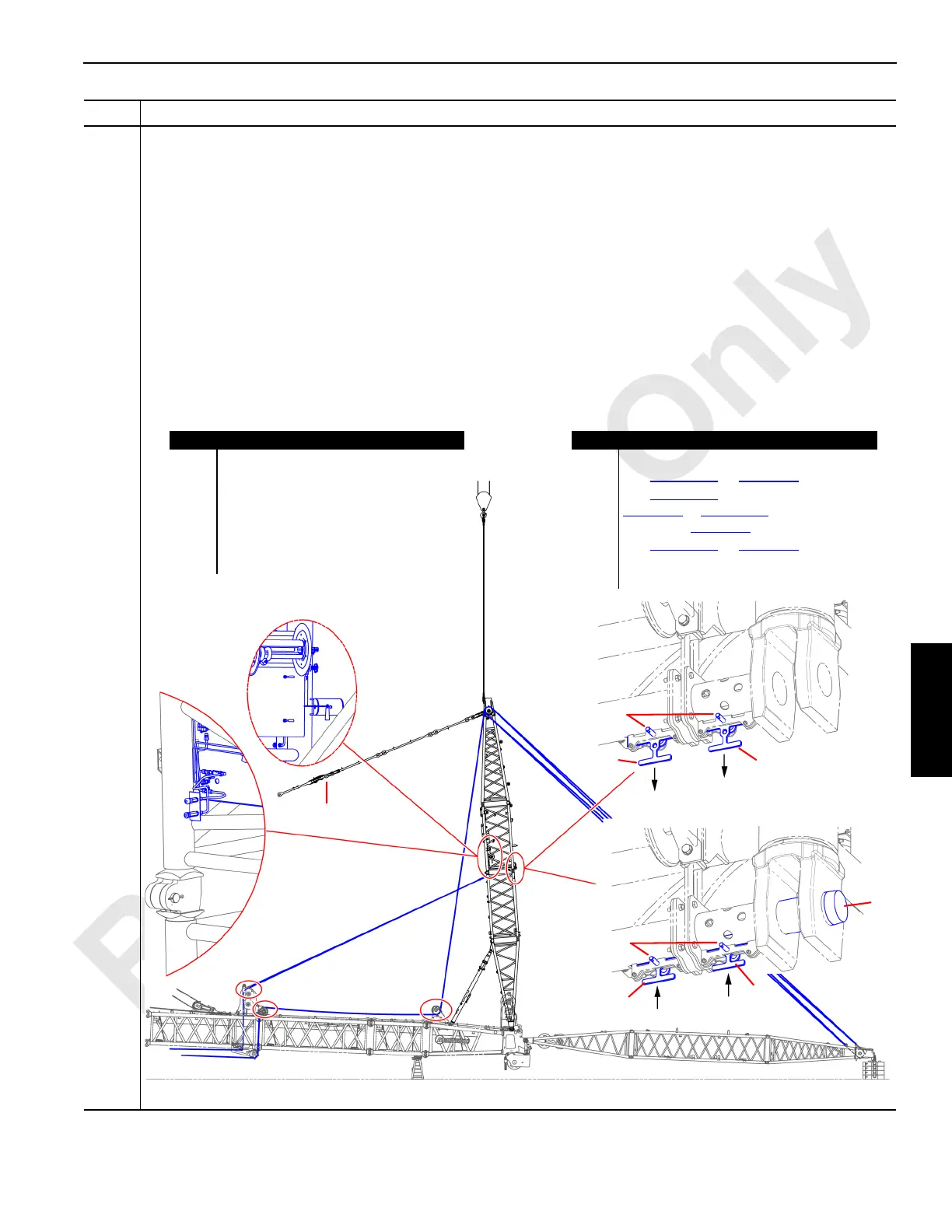
Information below from drawing A19443, Sheet 22:
Fasten the upper and lower sections of the main strut (A) and extend the jib backstay spreader (H):
• Ensure that the main strut connector pins (G) are both retracted.
• On both sides of the main strut (A), remove the quick release pins (D) and position the keeper plates (C) to the
pins retracted configuration (L). Put the quick release pins (D) back in.
• Connect the Arctic 15 hydraulic circuit of the Portable Power Unit (see Folio 2220) to the main strut hydraulic
connectors (B).
• Use the main strut pin puller hydraulic control (F) to extend the main strut connector pins (G) and lock the upper
and lower sections of the main strut together.
• Use the jib backstay spreader hydraulic control (E) to extend the jib backstay spreader (H).
• After the jib backstay spreader (H) has been extended, remove the quick release pins (D) on both sides of the
main strut and position the keeper plates (C) to the pins extended configuration (M).
• Disconnect the Portable Power Unit hydraulic lines from the main strut hydraulic connectors (B).
Step Action
FIGURE 4-44
Item Description
A Main strut.
B Main strut hydraulic connectors.
C Keeper plate.
D Quick release pin.
E Jib backstay spreader hydraulic control.
F Main strut pin puller hydraulic control.
G Main strut connector pin.
Item Description
H Jib backstay spreader.
I See Figure 4-19
on page 4-19.
J See Figure 4-25
(boom < 70m) on
page 4-25
or Figure 4-26 (boom 70m or
greater) on page 4-26
.
K See Figure 4-15
on page 4-15.
L Pins retracted configuration.
M Pins extended configuration.
A
B
C
C
D
E
F
G
H
I
J
K
L
M
C
C
D

 Loading...


