Do you have a question about the Manitowoc CVD2075 and is the answer not in the manual?
Alerts for potential personal injury and equipment damage situations.
Provides helpful information to perform procedures more efficiently.
Emphasizes proper installation, care, and maintenance for equipment performance.
States that routine adjustments and maintenance are not covered by warranty.
Warns against operating misused, abused, neglected, or modified equipment.
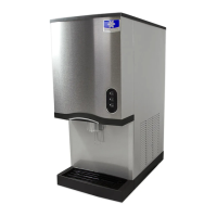
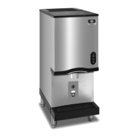
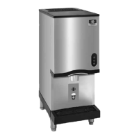
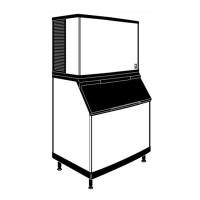
Lists the ice machine head sections and corresponding CVD® condensing units.
Notes that ice machine sequence of operation can differ by model.
Explains where to find the model and serial number for requesting information.
Highlights the requirement for an ice deflector with specific storage bins.
Explains the importance of returning the registration card to validate warranty.
Stresses mailing the registration card to validate the installation date.
Provides an overview of the warranty outline and where to get details.
Details the 3-year warranty on the ice machine and 5-year on evaporator/compressor.
Details the 3-year labor warranty and 5-year on evaporator labor.
Lists items excluded from warranty coverage, like maintenance and unauthorized modifications.
Clarifies the product is for commercial use only, not household.
Specifies that qualified and authorized service companies must perform warranty repairs.
Notes that normal maintenance is not covered by warranty.
Outlines criteria for selecting the ice machine head section location, including air quality and temperature.
Specifies minimum clearance requirements for the ice machine head section for operation and servicing.
Describes stacking requirements for Q0600C/Q0800C/Q1000C and limitations for Q1400C/QDUAL.
Explains when an ice deflector is necessary for QDUAL models and all models installed on a bin.
Specifies criteria for selecting the CVD® Condensing Unit location, including air temperature and airflow.
Details minimum clearance requirements for the condensing unit for operation and servicing.
Discusses local water conditions and potential treatment for scale, sediment, and chlorine.
Provides guidelines for installing water inlet lines, including temperature and pressure requirements.
Refers to separate instructions for installing a Manitowoc water filter system.
Gives guidelines for drain line installation to prevent backflow and ensure proper drainage.
Mentions local water conditions may require treatment for scale and sediment.
Provides guidelines for installing water lines for water-cooled condensers, including pressure and temperature limits.
Warns about exceeding water pressure limits at the condenser and available options.
Details requirements for draining condensate from the condensing unit, including level and drain line slope.
Presents electrical specifications for ice machines and condensing units, including voltage, fuse, and amps.
Emphasizes verifying compressor rotation for 3-phase CVD2075 to avoid voiding warranty.
Notes that the ice machine head section and condensing unit are wired independently.
Details electrical specifications for various CVD® Condensing Unit models, including voltage, breaker, and amps.
Warns about correct compressor rotation for CVD2075 3 Phase, noting incorrect rotation voids warranty.
States that standard condensing units will not operate QuietQube® ice machine heads.
Provides specifications for line sets, including suction line, liquid line, and insulation thickness.
Details the R-404A refrigerant charge from the factory for various models and line set lengths.
Warns not to exceed the nameplate charge for the refrigeration system.
Lists warranty exclusions related to modifications and non-Manitowoc parts.
Provides guidelines for installing refrigeration line sets to ensure proper oil return and system operation.
Warns that line set installation and brazing must be done by trained technicians.
Warns that QuietQube® machines will not function with line sets over 100 ft.
Illustrates and specifies the maximum allowable rise and drop distances for line sets.
Explains when and how to install oil traps in the suction line based on rise conditions.
Advises against forming unwanted traps or coiling excess tubing.
Describes the purpose of a service loop for access and installation requirements.
Lists Manitowoc S-Trap kits with corresponding models and tubing sizes.
Warns about specific configurations of rise and drop in line sets.
Details steps and precautions for connecting the line set to the ice machine head section, including valve protection.
Warns about the refrigerant charge in the head section and the need for closed valves.
Provides steps for connecting the line set to the condensing unit, emphasizing minimizing atmospheric exposure.
Warns about the factory pressure (nitrogen/helium) in the condensing unit and bleeding it off.
Recommends Schrader valve core removal tools to decrease evacuation time.
Details the process of pressure testing with nitrogen and evacuating to 250 microns.
Explains how to evacuate from the condensing unit side using Schrader valves.
Describes the procedure for opening the suction, liquid, and receiver service valves before starting.
Stresses the importance of reinstalling all refrigeration valve caps to prevent leaks.
Provides torque specifications for valve stems, caps, and Schrader cores.
Outlines the process of leak checking, powering up, and starting the ice machine.
Details insulation requirements for suction and liquid lines to prevent condensation.
Emphasizes the minimum insulation thickness required for preventing condensation.
Provides step-by-step instructions for insulating the suction shut-off valve.
Emphasizes verifying compressor rotation for CVD2075 3 Phase to avoid voiding warranty.
Presents data on the heat rejected by condensing units in A/C and Peak values.
Advises performing operational checks for the first time, after downtime, or after cleaning.
Notes that routine adjustments and maintenance are not covered by warranty.
Explains water level setting for these models and that it is not adjustable.
Details how to check and adjust the water level for Q1400C/SU1000C models using the float valve.
Describes how to inspect and adjust the ice thickness probe to maintain a 1/8 in. ice bridge.
Explains the harvest sequence water purge adjustment, its use with special water systems, and settings.
Recommends the factory setting of 45 seconds for water purge and discourages shorter settings.
Recommends cleaning and sanitizing every six months for efficient operation.
Stresses using only approved Manitowoc cleaners and sanitizers.
Warns against mixing cleaner and sanitizer solutions due to Federal law violations.
Advises wearing protective gear when handling cleaners or sanitizers.
Notes specific installation and cleaning procedures for SU1024YC on SerVend UC-300 dispensers.
Explains the technology allowing cleaning/sanitizing via a switch and its scope.
Describes the AuCS® accessory for automatic cleaning/sanitizing based on time intervals.
Explains AlphaSan® technology uses silver ions to control biofilm and prevent discoloration.
Details the steps for initiating and performing a cleaning cycle using Manitowoc's technology.
Warns against forcing ice from the evaporator to prevent damage.
Describes the end of the cleaning cycle, rinse cycles, and options for restarting ice making.
Details the steps for initiating and performing a sanitizing cycle.
Describes the end of the sanitizing cycle, its relation to bin sanitizing, and restart options.
Explains how the AuCS® accessory monitors cycles and initiates cleaning/sanitizing automatically.
Directs users to the AuCS® Accessory Guide for detailed information.
Notes that the curtain switch interrupts the cleaning/sanitizing sequence.
Provides steps for manually starting the automatic cleaning system.
Details steps for removing parts, including warnings and solution mixing ratios.
Warns not to immerse the water pump motor in cleaning solutions.
Explains how to determine if the water dump valve needs removal for cleaning.
Repeats the warning to disconnect power and water supply before proceeding.
Provides detailed steps for disassembling the water dump valve.
Stresses the importance of completely drying the plunger and enclosing tube before assembly.
Details the steps for removing the water pump assembly.
Describes how to remove the ice thickness probe for cleaning or replacement.
Details the steps for removing the water level probe.
Explains how to remove the splash shield for specific models.
Stresses the importance of reinstalling the splash shield to prevent water leakage.
Describes the steps for removing the water curtain.
Details the steps for removing the float valve for specific models.
Explains how to determine if the water inlet valve needs removal for cleaning.
Provides the procedure for removing, cleaning, and reinstalling the water inlet valve.
Details the steps for removing the water distribution tube.
Warns against forcing the removal of the water distribution tube.
Explains how to disassemble the water distribution tube for cleaning.
Describes the process for removing the water trough for specific models.
Details the procedure for removing the water trough for the SU1000C dispenser.
Outlines special precautions for removing the ice machine from service or exposure to freezing temperatures.
Warns about potential damage from water remaining in the machine during freezing temperatures.
Provides winterization steps for the CVD1476 water-cooled condensing unit.
Refers to the AuCS® Accessory manual for winterization procedures.
Identifies key components of the ice machine head section for specific models.
Provides an internal view of the ice machine head section showing component locations.
Identifies components for the SU1000C/SerVend UC-300 dispenser.
Identifies components for the Q1400C model.
Identifies components for the QDUAL model.
Identifies components of the CVD® Condensing Unit for specific models.
Identifies components of the CVD1476 Condensing Unit.
Identifies components of the CVD1875/CVD2075 Condensing Unit.
Details the initial start-up sequence, including water purge and refrigeration system start-up.
Explains the prechill and freeze stages of the ice making cycle.
Describes the water purge and harvest stages of the ice making cycle.
Explains the automatic shut-off process when the storage bin is full.
Details energized parts during different stages of the ice making sequence for specific models.
Lists energized parts during the ice making sequence for the Q1400C model.
Lists energized parts during the ice making sequence for the QDUAL model.
Describes general features of control boards, including safety limit controls.
Explains the primary and secondary functions of the Harvest/Safety Limit Light.
Details the freeze time lock-in feature that prevents short cycling.
Explains the safety feature that automatically initiates harvest after 60 minutes in freeze.
Describes the two built-in safety limits protecting the ice machine from failures.
Explains the three-minute delay initiated after an automatic shut-off on a full bin.
Discusses how inputs affect control board operation and where to find more details.
Explains the function of control board relays and notes they are not field replaceable.
Details the function and specifications of the main control board fuse.
Warns about high voltage present on the control board terminals.
Provides steps to check the fuse using a light indicator and an ohmmeter.
Explains the function and specifications of the bin switch, which controls harvest termination and auto shut-off.
States the water curtain must be closed (bin switch closed) to start ice making.
Details how to check the bin switch operation using a light indicator and physical movement.
Provides steps for performing an ohm test on the bin switch.
Explains how water curtain removal affects ice making and harvest sequences.
Describes the function and specifications of the ICE/OFF/CLEAN toggle switch.
Details how to check the toggle switch operation using an ohmmeter.
Explains how the ice thickness probe's electronic sensing circuit works to initiate harvest.
Details how to check and adjust the ice thickness probe for proper ice bridge thickness.
Provides information on how adjusting the probe affects ice thickness.
Advises ensuring the probe wire and bracket do not restrict probe movement.
Outlines a procedure for cleaning the ice thickness probe before diagnosing control circuitry.
Provides steps to diagnose issues when the ice machine does not cycle into harvest when water contacts the probe.
Continues diagnosing harvest light status to pinpoint control circuitry issues.
Addresses issues where the ice machine cycles into harvest before water contact with the probe.
Explains how to monitor the water level probe circuit using the water level light.
States the water level is set to maintain proper level and is not adjustable.
Describes the safety feature that limits water inlet valve on-time.
Explains how the water inlet valve and probe control water level during the freeze cycle.
Notes the water level probe does not control the water inlet valve during the harvest cycle water purge.
Details steps to diagnose water trough overfilling during the freeze cycle.
Emphasizes the importance of restarting the machine correctly before diagnostics.
Highlights the timing requirements for the diagnostic test to work properly.
Provides a chart for diagnosing water level control issues based on jumper wire connection.
Provides a chart for diagnosing water level control issues based on control board terminal connection.
Details steps to diagnose why water will not run into the sump trough during the freeze cycle.
Provides a chart for diagnosing water flow issues by disconnecting the probe.
Warns about high voltage present on the control board terminals.
Lists steps to diagnose why the ice machine head section will not run.
Lists steps to diagnose why the condensing unit will not run.
Explains how to check compressor winding resistance for single and three-phase compressors.
Describes how to check motor windings for continuity to ground.
Discusses causes of locked rotor current and how to diagnose them.
Explains how to check for high amperage draw during compressor start-up.
Describes how to test capacitors for failure, including visual checks and substitute testing.
Details how to check the relay's contacts and coil for proper operation.
Repeats the warning to disconnect electrical power before working on components.
Provides the electrical diagram for the ice machine head section of specific models.
Provides the electrical diagram for the SU1000C model.
Provides the electrical diagram for the Q1400C model.
Provides the electrical diagram for the QDUALC model.
Provides the electrical diagram for various CVD condensing units (1-phase).
Provides the electrical diagram for various CVD condensing units (3-phase).
Introduces refrigeration system diagnostics and initial checks.
Advises verifying water and electrical systems before diagnosing refrigeration components.
Explains the operation of the refrigeration system during the freeze cycle for air and water-cooled models.
Explains the operation of the refrigeration system during the harvest cycle.
Describes the function of the suction accumulator and its operation during freeze and harvest cycles.
Highlights the importance of correct refrigerant charge and the symptoms of over/undercharging.
Categorizes ice release issues into mechanical or refrigeration problems and how to differentiate.
Provides a checklist of common issues that prevent the harvest cycle from completing.
Details the procedure for performing an ice production check using formulas and charts.
Lists common installation and visual inspection problems with corrective actions.
Discusses how water-related problems can mimic refrigeration issues and must be identified first.
Lists common water system problems and their corrective actions.
Explains how analyzing ice formation patterns can help diagnose malfunctions.
Describes how evaporator tubing routing affects ice fill pattern failure modes.
Advises keeping the water curtain in place during pattern checks.
Describes normal ice formation and patterns indicating issues at the evaporator outlet.
Describes ice formation patterns indicating issues at the evaporator inlet, spotty formation, and no formation.
Notes that Q1400C & QDUALC have independent circuits that may operate differently.
Describes the control board's two built-in safety limits that protect the ice machine.
Details Safety Limit #1, which initiates harvest if freeze time reaches 60 minutes.
Details Safety Limit #2, which returns the machine to freeze if harvest time reaches 3.5 minutes.
Explains the stand-by mode for QDUALC after a safety limit shutdown.
Describes how to interpret safety limit indications on control boards with black microprocessors.
Describes how to interpret safety limit indications on control boards with orange labels.
Provides notes on diagnosing safety limits, including external problems and code erasure.
Introduces checklists designed to assist service technicians in analysis.
Lists potential causes for Safety Limit #1 failures across water, electrical, and refrigeration systems.
Lists potential causes for Safety Limit #2 failures across water, electrical, and refrigeration systems.
Explains how to determine operating conditions and perform a discharge pressure check.
Lists potential causes for high discharge pressure, including installation, condenser, charge, and other issues.
Lists potential causes for low discharge pressure, including installation, charge, and other issues.
Explains how suction pressure changes and factors affecting it, advising discharge pressure analysis first.
Provides a step-by-step example for analyzing suction pressure for a Q1000C model.
Lists potential causes for high suction pressure, including discharge pressure and refrigerant charge issues.
Lists potential causes for low suction pressure, including discharge pressure and refrigerant charge issues.
Describes the function of the cool vapor valve as an electrically operated valve.
Explains the normal operation of the cool vapor valve during freeze and harvest cycles.
Details the two failure modes of the cool vapor valve: not opening or remaining open.
Explains the importance of analyzing suction line temperature and provides a procedure to document it.
Stresses attaching the sensing device directly to the copper line.
Explains the purpose of the diagnostic charts and the need for prerequisite corrections.
Outlines the step-by-step procedure for using the diagnostic charts for analysis.
Describes how to determine the refrigeration problem based on the analysis results.
Identifies cool vapor valve leaking as a problem and suggests replacement.
Discusses low charge/TXV starving and the need to verify charge before replacing the valve.
Explains TXV flooding/overcharge causes and how to diagnose them.
Addresses compressor replacement and warranty credit requirements.
Provides diagnostic charts for single expansion valves on specific ice machine models.
Provides diagnostic charts for dual expansion valves on specific ice machine models.
Explains the function and operation of the Headmaster Control Valve in freeze cycle.
Notes that head pressure settings vary by QuietQube® model.
Describes the operation of controls during the harvest cycle and symptoms of headmaster valve failure.
Provides steps for diagnosing air-cooled condensing units during the freeze cycle.
Explains when the headmaster bypass functions properly and when malfunctions occur.
Lists failure modes and causes for Headmaster Control Valves on specific CVD models.
Lists failure modes and causes for Headmaster Control Valves on the CVD0675 model.
Explains the role of the water regulating valve in maintaining discharge pressure during the freeze cycle.
Lists symptoms of headmaster valve failure during the harvest cycle for water-cooled units.
Lists failure modes and causes for the Headmaster Control Valve on the CVD1476 model.
Explains the function of the water regulating valve in maintaining freeze cycle discharge pressure.
Provides steps to check the water regulating valve's operation and settings.
Lists potential problems with the water regulating valve during the freeze cycle.
Describes the function of the fan cycle control in managing the condenser fan motor.
Lists the specifications for fan cycle control cut-in and cut-out pressures for various models.
Provides steps for checking the fan cycle control's operation.
Explains the HPCO control's function in stopping the ice machine due to excessive high-side pressure.
Lists the specifications for HPCO control cut-out and cut-in pressures.
Details the procedure for checking the HPCO control's operation.
Warns about exceeding discharge pressure limits and stopping the machine.
Explains the LPCO control's function in energizing/de-energizing the contactor coil.
Lists the specifications for LPCO control cut-out and cut-in pressures.
Details the procedure for checking the LPCO control's operation.
Provides the tubing schematic for the refrigeration circuit of specific models.
Provides the tubing schematic for the refrigeration circuit of Q1400C/QDUALC models.
Explains that these charts are used as guidelines to verify correct ice machine operation.
Stresses the importance of accurate data collection for correct diagnosis.
Provides notes on zeroing manifold gauges and the location for pressure readings.
Presents data on cycle times, 24-hour ice production, and operating pressures for this model series.
Presents data on cycle times, 24-hour ice production, and operating pressures for this model series.
Presents data on cycle times, 24-hour ice production, and operating pressures for this model series.
Presents data on cycle times, 24-hour ice production, and operating pressures for this model series.
Presents data on cycle times, 24-hour ice production, and operating pressures for this model series.
Presents data on cycle times, ice production, pressures, and condenser water consumption for this model series.
Presents data on cycle times, 24-hour ice production, and operating pressures for this model series.
Presents data on cycle times, 24-hour ice production, and operating pressures for this model series.
Advises against purging refrigerant and recommends using recovery equipment.
States Manitowoc Ice is not responsible for contaminated refrigerant use.
Recommends replacing the liquid line drier before evacuating and recharging.
Details required connections for manifold gauge sets using low loss fittings.
Highlights the three connection points needed for complete system recovery/evacuation.
Outlines the step-by-step procedures for refrigerant recovery and evacuation.
States the receiver service valve must be accessed for complete refrigerant removal.
Illustrates the refrigerant recovery connection points on the Q1400C model.
Details the step-by-step procedure for charging the refrigeration system.
Advises checking for refrigerant leaks after installing valve caps.
Outlines basic requirements for restoring contaminated refrigeration systems.
States Manitowoc Ice is not responsible for contaminated refrigerant use.
Describes how to determine the severity of system contamination through inspection and testing.
Notes that Manitowoc Service procedures require refrigerant reuse if quality is not compromised.
Provides a chart correlating symptoms/findings with required cleanup procedures.
Details the procedure for cleaning systems with mild contamination.
Recommends dry nitrogen to prevent CFC release during the procedure.
Advises performing a pressure test as a preliminary leak check.
Outlines the steps for cleaning systems with severe contamination.
Advises against refrigerant sweeps as they release CFCs.
Continues the severe contamination cleanup procedure, including evacuation and filter-drier replacement.
Repeats the recommendation for using dry nitrogen.
Explains a procedure to replace components without removing refrigerant, reducing repair time.
States this is a required in-warranty repair procedure.
Warns against unsdering defective components and cutting them out instead.
Illustrates the use of the pinch-off tool for tubing manipulation.
Notes that tubing may not be perfectly re-rounded after using the tool.
Explains the difference between Manitowoc driers and off-the-shelf ones, emphasizing filtration and moisture/acid removal.
Lists recommended OEM field replacement liquid line driers with model, size, and part numbers.
States the liquid line drier is a warranty part and must be replaced when the system is opened.
Describes the function of the suction line filter and when it needs replacement.
Lists recommended OEM field replacement suction line filters with model, size, and part numbers.
States the information is for reference only and serial number tag overrides.
Provides refrigerant charge and line set length data for various models.
Notes that all listed machines use R-404A refrigerant.
Provides specific instructions for QDUAL models regarding line set lengths over 50 ft.
Specifies that Manitowoc ice machines use POE oil and recommends Mobil EAL22A lubricant.
Details the procedure for changing compressor oil when refrigeration systems are exposed to atmosphere.
Defines the process of recovering refrigerant.
Defines the process of recycling refrigerant for reuse.
Defines refrigerant reclamation and its required standards.
Refers to ARI Standard 700 for new product specifications.
Outlines Manitowoc's policy on refrigerant handling, reuse, and disposal.
Lists the types of refrigerants Manitowoc approves for use.
States that Manitowoc is not responsible for contaminated refrigerant use.