Section 2 Installation Instructions
Part Number 020003315 1/11 2-9
Water Supply
RECOMMENDED PLUMBING
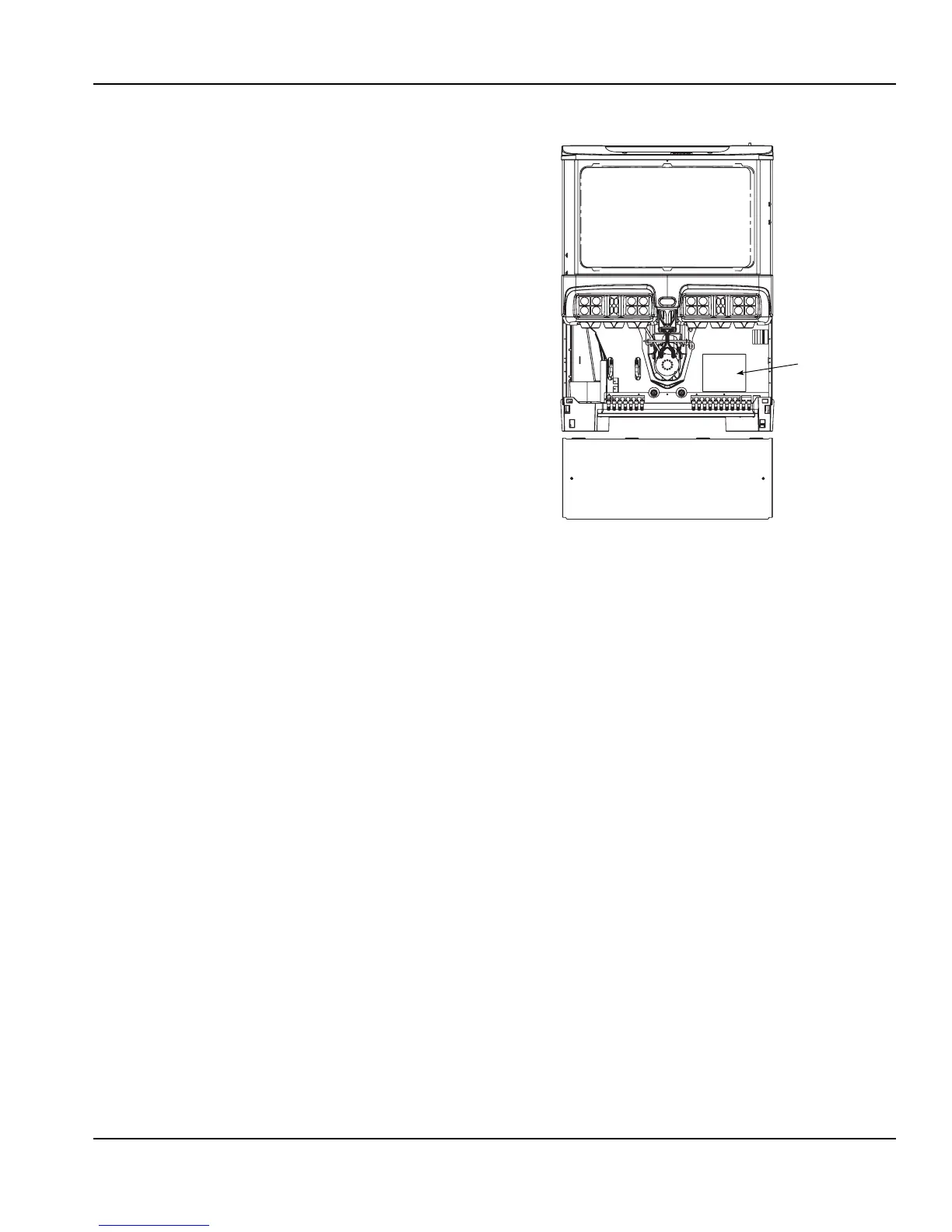
The plumbing diagram is printed on a white vinyl label,
normally located above the inlet tubes for syrup and
water. The plumbing diagram label can be accessed by
removing the splash panel of the dispenser. The
plumbing diagram label explains which inlet coldplate
fittings supply which dispenser valves and water
manifolds.
The water supply must first be connected to the
carbonator pump (not shown) before plumbing to
connection “A” shown on plumbing diagram. The
carbonator pump deck must be within six feet of the
dispenser for optimum performance. See BIB installation
diagram for system pressure settings.
A check valve must be installed in the water supply
line 3 feet from the noncarbonated water connection
“PW”. Contact factory if not installed.
DIAGRAM LOCATION
Splash Panel
Plumbing
Diagram
 Loading...