BOOM RT765E-2 SERVICE MANUAL
4-20
Published 9-04-2014, Control # 422-08
Removal And Installation
Removal and installation of the telescope cylinder from the
boom is described under disassembly and assembly of the
boom. Refer to Maintenance, page 4-2.
Disassembly And Assembly
Disassembly and assembly procedures of the telescope
control valve and cylinder are provided in Valves, page 2-30
and Telescope Cylinder Charge Valve Manifold (If
Equipped), page 2-58 respectively.Lift Circuit
Description
The boom lift circuit consists of the lift hydraulic remote
controller, lift directional control valve, holding valve, and the
lift cylinder. These components enable the boom to be raised
or lowered to various degrees of elevation ranging from -3 to
+78 degrees from horizontal.
The lift directional control valve is the closed spool type and
is described in Valves, page 2-30.
Refer to Valves, page 2-30 for a complete description of the
hydraulic remote controller.
The lift cylinder has a 30.48 cm (12.0 in) bore. Both are the
double acting type. Dirt and other foreign material is
prevented from entering the cylinder and causing internal
damage by a wiper seal during rod retraction. Oil Seals on
both the piston and cylinder head prevent internal and
external hydraulic oil leakage. Refer to Telescope Cylinder
Charge Valve Manifold (If Equipped), page 2-58 for a
complete description of the lift cylinder.
The holding valve is a balanced poppet type hydraulic valve.
It is threaded into the port block which is an integral portion of
the lift cylinder barrel. The holding valve functions when
booming up (cylinder rod extended), booming down (cylinder
rod retracted), or holding (cylinder rod stationary).
Theory of Operation
The directional control valve bank housing the lift control
valve is supplied by flow from the hydraulic pump.
When booming up, oil unseats the poppet (check) valve in
the holding valve, letting oil flow to the piston side of the
cylinder. Pressure is applied to the piston, forcing the rod to
extend, raising the boom.
When booming down, oil enters the retract port of the port
block and flows to the cylinder rod side. When pilot pressure
reaches a pre-determined value, the main poppet unseats
and oil flows from the piston side of the cylinder to the
reservoir.
All return flow from the control valve goes to the reservoir.
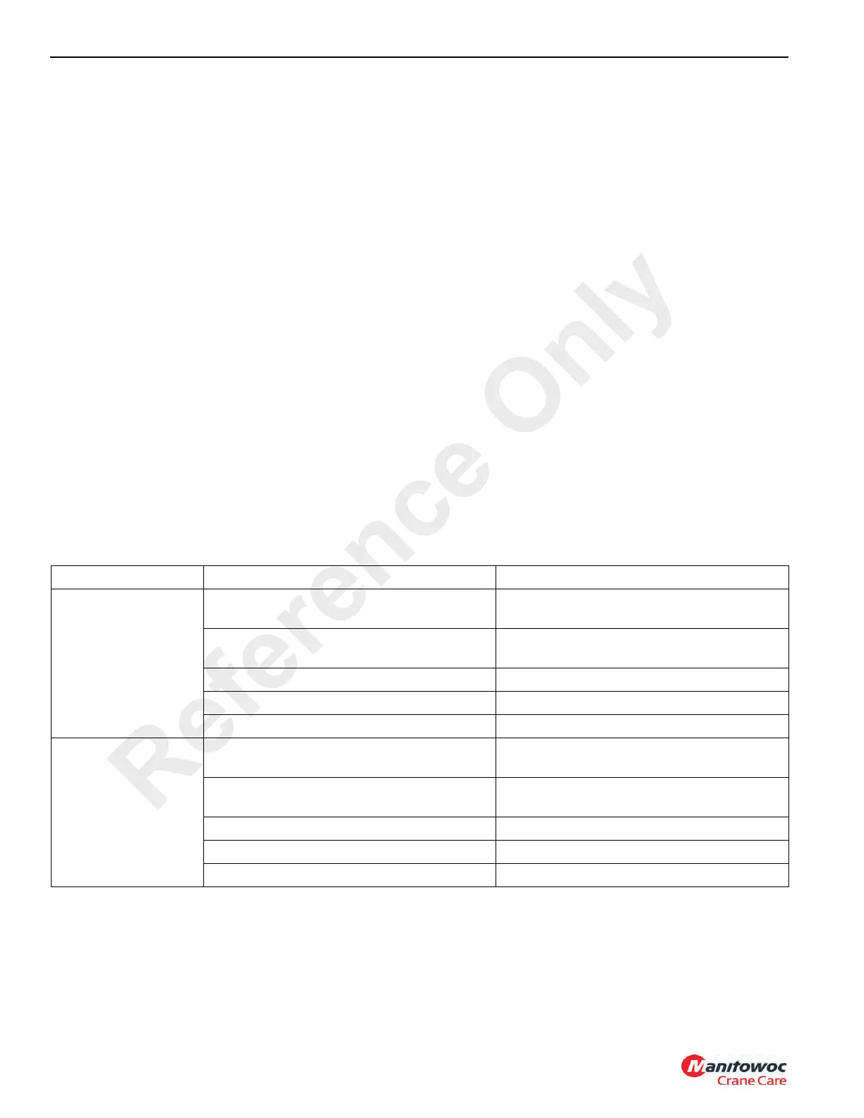
Maintenance
Symptom Probable Cause Solution
1. Boom raises
erratically.
a. Low hydraulic oil. a. Check system for leaks. Make repairs
as needed. Fill reservoir.
b. Low engine rpm. b. Increase engine rpm to recommended
setting.
c. Main relief valve damaged. c. Replace relief valve.
d. Air in cylinder rod. d. Bleed cylinder rod.
e. Bent boom pivot shaft. e. Replace pivot shaft.
2. Boom lowers
erratically.
a. Low hydraulic oil. a. Check system for leaks. Make repairs
as needed. Fill reservoir.
b. Low engine rpm. b. Increase engine rpm to recommended
level.
c. Circuit and/or relief valve inoperative. c. Repair or replace relief valve.
d. Air in hydraulic cylinder. d. Bleed air from cylinder.
e. Damaged hydraulic pump section. e. Repair or replace pump section.
Reference Only
 Loading...


