6-22
Published 9-04-2014, Control # 422-08
SWING SYSTEM RT765E-2 SERVICE MANUAL
SWING LOCK PIN
Description
The purpose of the swing lock pin is to lock the
superstructure in position directly over the front for pick and
carry loads. The pin swing lock installation consists of a large
pin, a control handle in the right side of the cab, and control
linkage that allows the crane operator to set and free the pin.
When the superstructure is directly over the front, pushing
the control handle down drops the swing lock pin into a
socket on the carrier frame, locking the superstructure in
place. Pulling the control handle up pulls the pin out of the
socket, unlocking the superstructure.
Maintenance
Verify linkage is installed to avoid damage from
superstructure rotation and is undamaged. Verify pin,
turntable bushing pin passes through, and socket on the
frame are undamaged. Verify all attaching hardware is
secure and undamaged.
Ensure linkage is adjusted properly. If it is, the pin bottom will
stick out about 2.32 in (5.89 cm) from the bottom of its
bushing in the turntable. (If it is too far in, it might not lock
properly. If it is too far out, it might hang up). Using the jam
nuts on the linkage parts, adjust the linkage so the pin bottom
will stick out about 2.32 in (5.89 cm) from the bottom of its
bushing in the turntable; verify the superstructure can lock
properly and the superstructure can rotate without lock pin
hangup.
360° SWING LOCK CONTROL (POSITIVE
LOCK TYPE) (OPTIONAL)
Description
The purpose of the swing lock is to secure the superstructure
in position at one of the positions in its rotation. There are
roughly 120 spots about 3.0 degrees apart for the
superstructure to lock to in its 360 degree of rotation. The
360 degree swing lock control lever is on the right side of
cab. Pushing the swing lock control lever down engages the
lock between the teeth of the swing gear. Pulling the swing
lock control lever up disengages the lock.
Maintenance
Verify cable is routed to avoid damage from superstructure
rotation and is undamaged. Verify swing lock assembly is
undamaged and working properly. Verify spring is
undamaged and has enough strength to pull blade of swing
lock assembly completely out of the gear teeth when the
control lever is up. Verify the linkage can put the blade of the
swing lock assembly as far as possible between the gear
teeth when the control lever is down. Verify all attaching
hardware is secure and undamaged. Make adjustments as
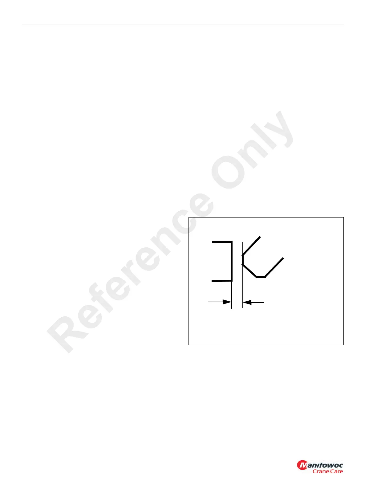
needed. When the lever is fully up, the top diagonal surface
of the blade of the swing lock assembly (the beveled surface
from the blade’s top horizontal surface to its “ax blade”
vertical surface should be 0.57 in (1.45 cm) from the tips of
the gear teeth.
If the swing lock assembly is damaged, install a replacement.
Align the blade of the swing lock assembly so it will fall
between gear teeth. Use the shim and the related attaching
hardware (two 5/16-18 screws and 5/16 ID lockwashers) to
ensure the swing lock assembly cannot move side to side,
and can lock up the superstructure. Torque the four 3/4-10
mounting bolts to their specified torque found in Fasteners
and Torque Values, page 1-16.
Gear Tooth
(typical)
Swing Lock
Assembly Blade
0.57 inch
(1.45 cm)
FIGURE 6-7
7069
Reference Only
 Loading...


