Home
Manitowoc
Construction Equipment
Grove RT765E-2
Manitowoc Grove RT765E-2 Service And Maintenance Manual
5
of 1
of 1 rating
330 pages
Give review
Manual
Specs
To Next Page
To Next Page
To Previous Page
To Previous Page
Loading...
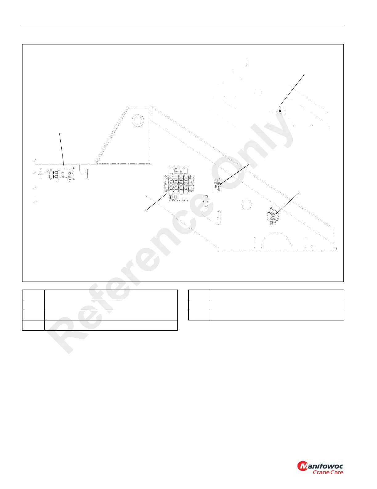
HYDRAULIC SYSTEM
RT765E
-2 SERVICE MANUAL
2-32
Published 9-04-2014, Control # 422-08
Superstructure
7539-1
FIGURE
2-
18
1
2
3
4
7539-2
5
Item
Description
1
Counterweight Removal Manifold
2
Directional Control V
alve (Hoist/Lift/T
ele)
3
Swing Brake and Armrest Lockout Manifold
Item
Description
4
S
teering Priority/Swing Control V
alve
5
Dual Accumulator Control V
alve
Reference
Only
69
71
Table of Contents
Table of Contents
5
Section 1
13
Overview of Manuals
13
Customer Support
14
General Crane Design
14
Specific Crane Description
14
Lifting Capacities (Load Chart)
14
Basic Components
14
Axle Weight Distribution
14
Serial Number Location
14
Transportation and Lifting Data
14
List of Specifications
15
General
15
Dimensions
15
Capacities
15
Torque Converter
15
Transmission
15
Engine
15
Axles
15
Brakes
15
Wheels and Tires
15
Hoists
16
Crane Nomenclature
19
General Maintenance
21
Cleanliness
21
After Cleaning
21
Removal and Installation
21
Disassembly and Assembly
21
Pressing Parts
22
Locking Devices
22
Wires and Cables
22
Shims
22
Hoses and Tubes
22
Bearings
23
Gaskets
23
Batteries
23
Hydraulic Systems
24
Hydraulic Fittings
25
Electrical System
26
Fatigue of Welded Structures
27
Loctite
27
Fasteners and Torque Values
28
Weld Studs
31
Wire Rope
32
General
32
Environmental Conditions
32
Dynamic Shock Loads
32
Lubrication
32
Precautions and Recommendations During Inspection or Replacement
32
Wire Rope Inspection (Running Ropes and pendant Cables)
33
Wire Rope Inspection (Boom Extension and Retraction Cables)
34
Wire Rope Inspection/Replacement (All Wire Rope)
34
Seizing Wire Rope
35
Installing 35X7 Class Wire Rope
36
Procedures for Cutting and Preparing 35X7 Class Wire Rope
36
Section 2
39
Description
40
Hydraulic Symbols
41
Maintenance
43
Preparation
43
Hydraulic System Maintenance Precautions
43
Label Parts When Disassembling
43
Hydraulic Oil Recommendations
43
Draining and Flushing
43
Removing Air from the Hydraulic System
44
Parts Replacement
45
Directional Control Valves
45
Supply Pressure and Return Circuit
47
Description
47
Pump Distribution
48
Troubleshooting
48
Troubleshooting Aids
50
Troubleshooting Procedures
50
Hydraulic Oil Return Filter Assembly
51
Fill Cap/Breather
51
Oil Cooler
53
Description
53
Oil Temperature Switches
53
Hydraulic Pumps
55
Description
55
Maintenance
55
Pump Disconnect Assembly
59
Disassembly
59
Assembly
59
Pressure Setting Procedures
61
Procedure a - Main Control Valve Reliefs
62
Procedure B - Main Directional Control Valve Pilot Supply Pressure
63
Procedure C - Swing Brake Pilot Supply Pressure
63
Procedure D - Brake Charge Supply Valve Relief Pressure
63
Procedure E - Charge Air Cooler Valve Relief Pressure
64
Procedure F - Brake Dual Accumulator Charge Valve Pressure Limits
64
Procedure G - Accumulator Pre-Charge Pressure
64
Procedure H - Precharging the Accumulator
65
Procedure I - Swing Valve Work Port Reliefs Pressure
65
Procedure J - Front Steer Relief Valve Pressure
66
Procedure K - Outrigger/Rear Steer Valve Relief
66
Procedure L - Hydraulic Oil Cooler Fan Motor Control Valve
66
Procedure M - Counterweight Removal Valve
67
Valves
68
General
68
Directional Control Valves
71
Description
71
Maintenance
71
Hydraulic Remote Control Valve
76
Description
76
Maintenance
76
Dual Accumulator Charge Valve
79
Description
79
Maintenance
79
Swing Brake and Armrest Lockout Valve Manifold
81
Description
81
Maintenance
81
Holding Valve
83
Description
83
Maintenance
83
Boom Lock Valve
83
Outrigger/Rear Steer Valve
85
Description
85
Maintenance
86
Outrigger Control Manifold
87
Description
87
Maintenance
88
Parking Brake/Range Shift Valve
89
Description
89
Maintenance
89
Axle Oscillation Lockout Valve
91
Description
91
Maintenance
91
High Speed Boost Selector Valve
92
Description
92
Maintenance
92
Hydraulic Accumulator
93
Description
93
Maintenance
93
Service Brake and CAC Fan Motor Priority Flow Control Valve
94
Description
94
Maintenance
94
Oil Cooler Fan Motor Priority Flow Control Valve
95
Description
95
Maintenance
95
Oil Cooler Fan Motor Priority Flow Control
95
Telescope Cylinder Charge Valve Manifold (if Equipped)
96
Description
96
Maintenance
96
Valve
96
Description
98
Cylinders
99
General
99
Maintenance
99
Surface Protection for Cylinder Rods
99
Temperature Effects on Hydraulic Cylinders
100
Lift Cylinder
102
Description
102
Maintenance
102
Lower Telescope Cylinder
106
Description
106
Maintenance
106
Upper Telescope Cylinder
110
Description
110
Maintenance
110
Axle Oscillation Lockout Cylinder
113
Description
113
Maintenance
113
Steer Cylinder
116
Description
116
Maintenance
116
Outrigger Extension Cylinder
119
Description
119
Maintenance
119
Outrigger Jack Cylinder
122
Description
122
Maintenance
122
Counterweight Removal Cylinder
125
Description
125
Maintenance
125
Description
129
General
129
Alternator
131
Batteries
131
Cab Electrical Panel
131
Carrier Electrical Panel
133
Maintenance
135
General
135
General Troubleshooting
136
Troubleshooting Swivel-Caused Electrical Problems
136
Connector Troubleshooting
136
Alternator/Charging System Troubleshooting
137
Alternator Replacement
139
Starter Replacement
139
Battery Replacement
140
Relay Panel Component Replacement
140
Gauge Cluster Replacement
141
Rocker Switch Replacement
141
Ignition Switch Replacement
142
Turn Signal Lever and Transmission Shift Lever Replacement
143
Windshield Wiper Assembly Replacement
145
Windshield Washer Assembly Replacement
146
Skylight Wiper Assembly Replacement
146
Telescope Cylinder Charge System - Electrical Schematic (if Equipped)
148
Tools for Troubleshooting
149
Optional Equipment
149
Beacon Light
149
Boom Mounted Floodlights
149
Rear View Mirror
149
Air Conditioner
149
Cold Weather Operation
149
Section 4
151
Description
151
Theory of Operation
151
Boom Extension
151
Boom Retraction
152
Maintenance
152
Removal
152
Boom Extension
152
Disassembly
157
Boom Nose Sheaves
159
Assembly
160
Installation
160
Installation
163
Functional Check
164
Inspection
164
Boom Alignment and Servicing
164
Cam Operated Check Valve Adjustment
165
Guide Block Adjustment
165
Boom Extension and Retraction Cable
166
Maintenance
166
Inspection
166
Adjustment
166
Telescope Circuit
167
Description
167
Theory of Operation
167
Maintenance
168
Description
170
Theory of Operation
170
Maintenance
170
Lift Cylinder Removal
172
Disassembly and Assembly
172
Lift Cylinder Installation
172
Swingaway Boom Extension
174
Description
174
Maintenance
174
Description
182
Description
183
Theory of Operation
183
Maintenance
184
Warm-Up Procedure
184
Hoist Area Access
184
Removal
186
Installation
186
Functional Check
186
Fluid Level
186
Description
186
Usage and Inspection
187
Preventative Maintenance
187
Oil Sampling
189
Brake Test Procedure
189
Hoist to Boom Alignment
190
Preparation
190
Tools Required
190
Procedure
190
Motor and Brake
192
Description
192
Idler Drum and Cable Follower
193
Description
193
Maintenance
193
Description
194
Third Wrap Indicator (Optional-Standard on CE)
196
Description
196
Maintenance
196
Third Wrap Indicator
196
On CE)
196
Hoist Drum Rotation Indicator System
197
Description
197
Maintenance
197
Hoist Control Valves
199
Description
199
Fixed Counterweight
200
Description
200
Maintenance
200
Counterweight Plate
200
Removable Counterweight (Optional)
202
Removal
202
Installation
202
Description
205
Theory of Operation
205
Swing Drive
205
Swing Brake
205
Swing Drive
206
Maintenance
207
Swing Brake
209
Swing Motor
211
Description
211
Maintenance
211
Swing Gearbox and Brake
212
Description
212
Maintenance
212
Swing Bearing
214
Description
214
Maintenance
214
Swivels
219
Description
219
Description
220
Hydraulic Swivel
221
Description
221
Theory of Operation
221
Maintenance
221
Two Port Water Swivel
223
Description
223
Maintenance
223
Electrical Swivel
224
Description
224
Theory of Operation
224
Maintenance
224
Swing Lock Pin
226
Description
226
Maintenance
226
360° Swing Lock Control (Positive Lock Type) (Optional)
226
Engine
227
Description
227
Maintenance
228
Electronic Control System
230
Description
230
Engine Control System Switches and Indicator Lights
230
Fuel System
233
Description
233
Maintenance
233
Description
234
Air Intake and Exhaust System
235
Description
235
Air Intake
235
Charge-Air Cooler System
239
Muffler
240
Water Cooling System
243
Description
243
Maintenance
243
Drive Train
248
Description
248
Maintenance
248
Transmission/Torque Converter
250
Description
250
Theory of Operation
250
Maintenance
251
Troubleshooting Procedures
251
Towing or Pushing
254
Description
255
Maintenance
256
Wheels and Tires
258
Typical Wear Patterns
258
Description
258
Maintenance
258
Steering Systems
261
Description
261
Theory of Operation
261
Maintenance
262
Rear Steering System
263
Troubleshooting
263
Hydraulic Pumps
264
Front Steering Control Valve
264
Integrated Outrigger/Rear Steer Control Valve
264
Steer Cylinders
264
Rear Axle Oscillation Lockout System
265
Description
265
Theory of Operation
265
Axle Oscillation Lockout Cylinders
267
Axle Oscillation Lockout Valve
267
Maintenance
267
Brake System
267
Description
267
Theory of Operation
268
Maintenance
269
Service Brakes
270
Description
270
Maintenance
270
Corrosion Protection
274
Parking Brake Actuator
276
Description
276
Maintenance
276
Parking Brake
277
Description
277
Maintenance
277
Park Brake Solenoid Valve
280
Description
280
Maintenance
280
Outrigger
280
Outrigger Circuit
280
Maintenance
281
Outrigger Beam
284
Extension Cylinder
288
Outrigger Monitoring System (Optional-Standard in North America)
288
Jack Cylinder
289
Outrigger Control Valves
290
General
291
Environmental Protection
291
Standard Lubricants
291
Arctic Lubricants and Conditions
293
Surface Protection for Cylinder Rods
296
Wire Rope Lubrication
296
Lubrication Points
297
Cranelube
297
Safety
297
Steering and Suspension
298
Drive Train
302
Drive Train (Continued)
304
Turntable
306
Outriggers
308
Boom
310
Boom (Continued)
312
Hoist
316
Hydraulic
318
Carwell® Rust Inhibitor
321
Protecting Cranes from Rusting
321
Cleaning Procedures
321
Inspection and Repair
322
Application
322
Areas of Application
322
Other manuals for Manitowoc Grove RT765E-2
Operator's Manual
178 pages
5
Based on 1 rating
Ask a question
Give review
Questions and Answers:
Need help?
Do you have a question about the Manitowoc Grove RT765E-2 and is the answer not in the manual?
Ask a question
Manitowoc Grove RT765E-2 Specifications
General
Brand
Manitowoc
Model
Grove RT765E-2
Category
Construction Equipment
Language
English
Related product manuals
Manitowoc Grove RT770E
174 pages
Manitowoc Grove RT890E
24 pages
Manitowoc Grove RT540E
160 pages
Manitowoc Grove RT9130E
28 pages
Manitowoc Grove RT530E-2
168 pages
Manitowoc GROVE GMK3060
906 pages
Manitowoc Grove GRT9165
476 pages
Manitowoc Grove YB5515-2
152 pages
Manitowoc GROVE GMK5150L
1040 pages
Manitowoc GROVE GMK 6400
960 pages
Manitowoc Grove GMK 5250L
958 pages
Manitowoc Grove GMK4100L-1
1016 pages
 Loading...


