OPERATING CONTROLS AND PROCEDURES RT770E OPERATOR MANUAL
3-18 Published 04-04-2017, Control # 446-09
When the control handle is pulled out, the pin is pulled out of
the socket, unlocking the superstructure.
12V Receptacle
This 12 volt accessory outlet (7) (Figure 3-10) is located on
the lower part of the control panel and is designed to mate
with most 12 volt adapter plugs.
Diagnostic Connector
The Diagnostic Connector (8) (Figure 3-10) is located on the
lower part of the front control panel. It is used for servicing
the crane’s electrical system.
A laptop computer with a nine pin cable connector and the
appropriate service software are required. Contact your local
Grove distributor or Manitowoc Crane Care for assistance.
Bubble Level Indicator
The Bubble Level Indicator (9) (Figure 3-10) is located by the
house lock control on the right side of the crane. The
indicator provides the operator with a visual aid in
determining the levelness of the crane.
Hoist Third Wrap Indicator (Optional—
Standard on CE)
The Hoist 3rd Wrap Indicator (10) (Figure 3-10) is located on
the right side console. The indicator will illuminate red when
three wraps or less of cable remain on either hoist.
Cold Weather Indicator (Optional)
The optional Cold Weather Indicator (11) (Figure 3-10) is
located on the right side console. The indicator comes on
when ambient temperature is at or below -29°C (-20°F). It
serves as a warning for the operator to stop operation in
extreme cold.
Ambient Temperature LED Indicator
The Ambient Temperature LED Indicator (12) (Figure 3-10)
is located on the right side console. When the ambient
temperature outside the crane reaches below -29°C (-20°F)
the LED indicator will illuminate and send a signal to the RCL
system. This temperature control is to prevent operation of
crane lifting functions in temperatures below -29°C (-20°F).
The system will initiate lockout of the following crane
functions: hoist up, boom down, and boom telescope-
extend. Hoist lowering, boom up and boom telescope-retract
along with lockout override, will still be operational to lower
the load.
Boom Not Synchronized Indicator
The Boom Not Synchronized Indicator (13, Figure 3-10) is
located on the right side console and is controlled by the
rated capacity limiter (RCL). It illuminates red when the RCL
senses that the boom sections are not synchronized. The
Boom Manual/Automatic Mode Selector Switch (13,
Figure 3-4) and Boom Section 1/Section 2 Selector Switch
(11, Figure 3-4) are used together to manually control the
extension and retraction of the boom sections to re-
synchronize the boom with the RCL.
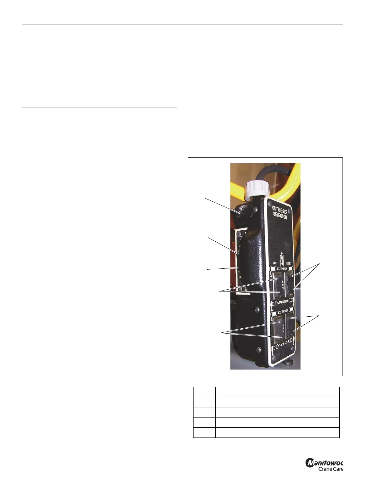
OUTRIGGER CONTROL
.
CAUTION
Swing Lock Damage!
Do not engage the Pin Swing Lock while superstructure is
in motion. Center boom over the front and engage Pin
Swing Lock to prevent superstructure rotation during
travel.
Item Description
1 Outrigger Control Box
2 Right Front Extension/Jack Cylinder
3 Left Front Extension/Jack Cylinder
4 Right Rear Extension/Jack Cylinder

 Loading...


