Grove Published 04-04-2017, Control # 446-09 3-19
RT770E OPERATOR MANUAL OPERATING CONTROLS AND PROCEDURES
The Outrigger Control Box (1, Figure 3-11) is stowed in the
cab (Figure 3-1) and is used to control the outriggers from
inside the cab.
NOTE: The park brake must be engaged for the outriggers
to operate.
Extend/Retract Switch
The Extend/Retract Switch (6,7 Figure 3-11) is located on
the side of the Outrigger Control Box and is used in
conjunction with the Outrigger Selector Switches (2,3,4,5
Figure 3-11) to control the outrigger functions.
Outrigger Selector Switches
There are four Outrigger Selector Switches (2,3,4,5
Figure 3-11) on the Outrigger Control Box. To extend or
retract an outrigger component, first select the component
with the Outrigger Selector Switch (2,3,4,5), then select
extend or retract with the Extend/Retract Switch (6,7
Figure 3-11).
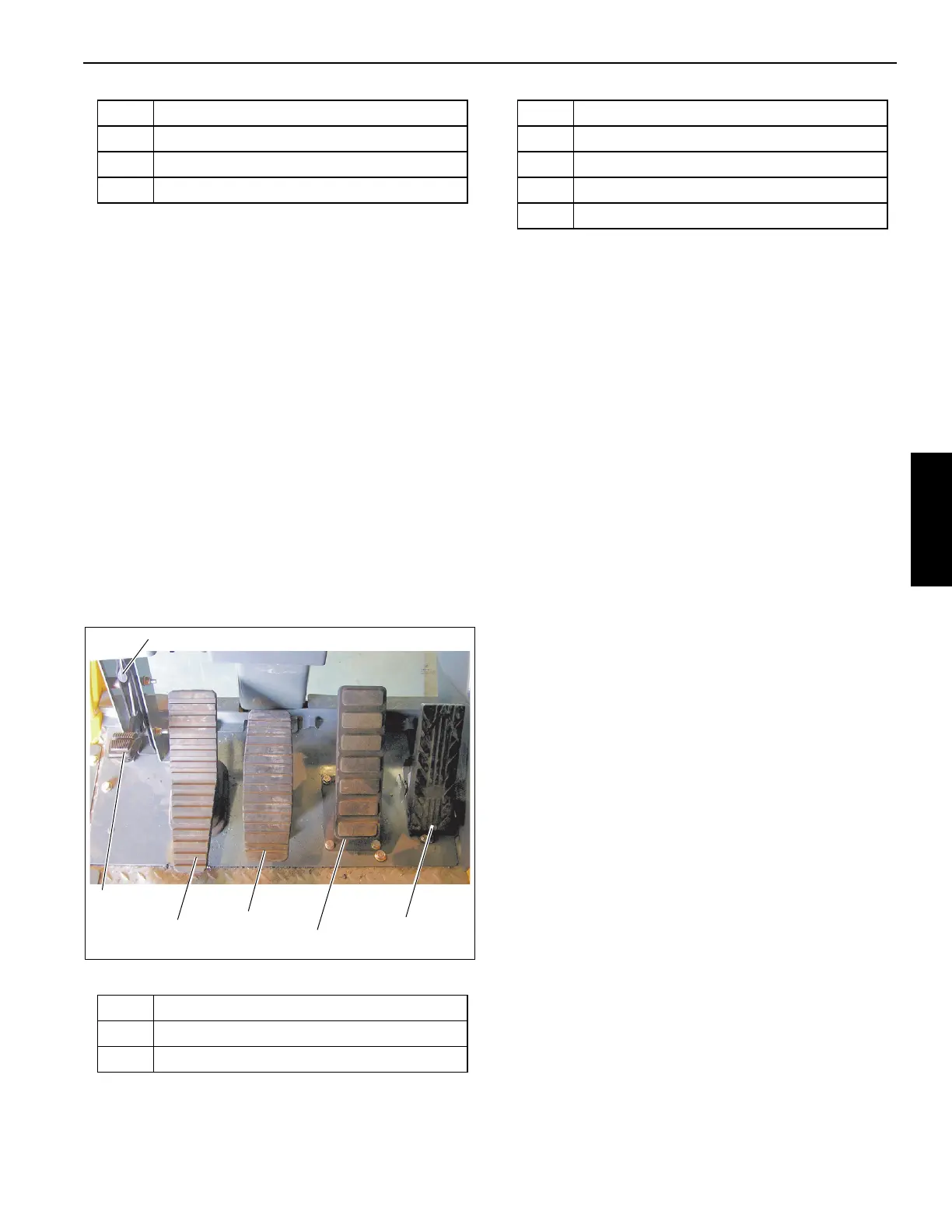
FOOT PEDAL CONTROLS
Figure 3-12 Item Numbers
360° Swing Lock Pedal
The 360° Swing Lock Pedal (1) (Figure 3-12) is located on
the left side of the crane cab floor. The pedal is used to
activate the swing lock to prevent the turret from turning. To
release the swing lock, pull up on the 360° Swing Lock
Release Lever (2).
Swing Brake Pedal
The Swing Brake Pedal (3) (Figure 3-12) is located on the
left side of the cab floor. The swing brake pedal is used to
actuate the swing brake to slow or stop swing motion.
Braking is proportional to pedal depression. With the pedal
not depressed and the swing brake control valve
disengaged, hydraulic pressure is applied to the brake,
overcoming spring pressure and releasing the brake.
Depressing the pedal actuates a swing power brake valve to
apply pressure to the brake assembly. This pressure aids the
spring pressure to overcome the hydraulic pressure being
applied to the brake release circuit and applies the spring
brake according to the pressure from the swing power brake
valve.
Telescope Control Foot Pedal (Optional)
The Telescope Control Foot Pedal (4) (Figure 3-12) is
supplied when the crane is equipped with an auxiliary hoist,
is located on the left side of the cab floor. Pushing forward on
the top of the pedal will extend the boom and pushing down
on the bottom of the pedal will retract the boom.
Service Brake Foot Pedal
The Brake Foot Pedal (5) (Figure 3-12) is the second pedal
from the right on the cab floor. Depressing the pedal controls
the application of the service brakes.
Foot Throttle Pedal
The Foot Throttle Pedal (6) (Figure 3-12) is located under
the RCL display module, on the floor. It is used to control
engine RPM which increases or decreases proportionately
with the amount of foot pressure applied to the pedal. The
pedal is electrically connected to the superstructure control
module which sends the signal to the engine ECM via the
J1939 data link.
5 Left Rear Extension/Jack Cylinder
6 Retract O/R
7 Extend O/R
Item Description
1 360° Swing Lock Pedal
2 360° Swing Lock Release Lever
Item Description
3 Swing Brake Pedal
4 Telescope Control Foot Pedal (Optional)
5 Service Brake Foot Pedal
6 Foot Throttle Pedal
Item Description

 Loading...


