3736
②
②
5. Reinstall the PCB controller and replace the front cover of unit.
Gas piping should be sized, installed, and tested only by a licensed
professional! Improper installation can result in improper equipment
performance or a hazardous situation.
1. Check the fuel gas type before installation. DO NOT connect a unit if the gas type
is not compatible. Contact your dealer for the proper unit to match the gas type.
2. Check the gas inlet pressure immediately upstream at a location provided by the
gas company. Ensure the gas pressure is within the limits shown in the
Specifications section.
3. Review the installation location taking into account all gas users on site. Calculate
the gas piping that will be required to service the installation. The gas supply line
shall be sized and installed to provide a supply of gas sufficient to meet the
maximum demand of the heater and all other gas consuming appliances at the
location.
Note: Reference the National Fuel Gas Code, NFPA 54, for proper line sizing.
4. Ensure any compound used on the threaded joints of the gas piping is compatible
with LPG/Propane or Natural Gas.
5. Use only approved materials to connect the unit to the gas line.
6. Install a manual gas valve in the gas supply line to the water heater. For best
performance the water heater should be the first user downstream from the gas
supply meter. A union can be used on the heater sized of the valve to allow for future
servicing or disconnection of the unit.
7. Manufacturer recommends installation of gas pressure regulator (ex. Maxitrol
325-5A or equivalent) on gas line to ensure gas pressure is at optimum level for
proper unit operation.
8. Purge the gas line of any debris and liquid before connection to the water heater.
9. Connect to the water heater.
10. Leak check all joints including the heater for gas tightness. Use a leak detection
solution, soap and water, or an equivalent nonflammable solution, as applicable.
8. Attach the wires to the terminal connectors using Y shaped crimp connections or
wrap the thermostat wires around the screws then fasten the screws to secure the
terminal connectors. Inspect and insure that the Y connectors or the thermostat
wires are not touching each other.
9. Mount controller to wall by drilling 2) 6mm holes 92mm (4") apart at installation
location, and insert the Expansion Anchors supplied.
10. Remove the panel cover from the remote base, secure remote base to wall with
(provided) screws.
11. Replace front cover.
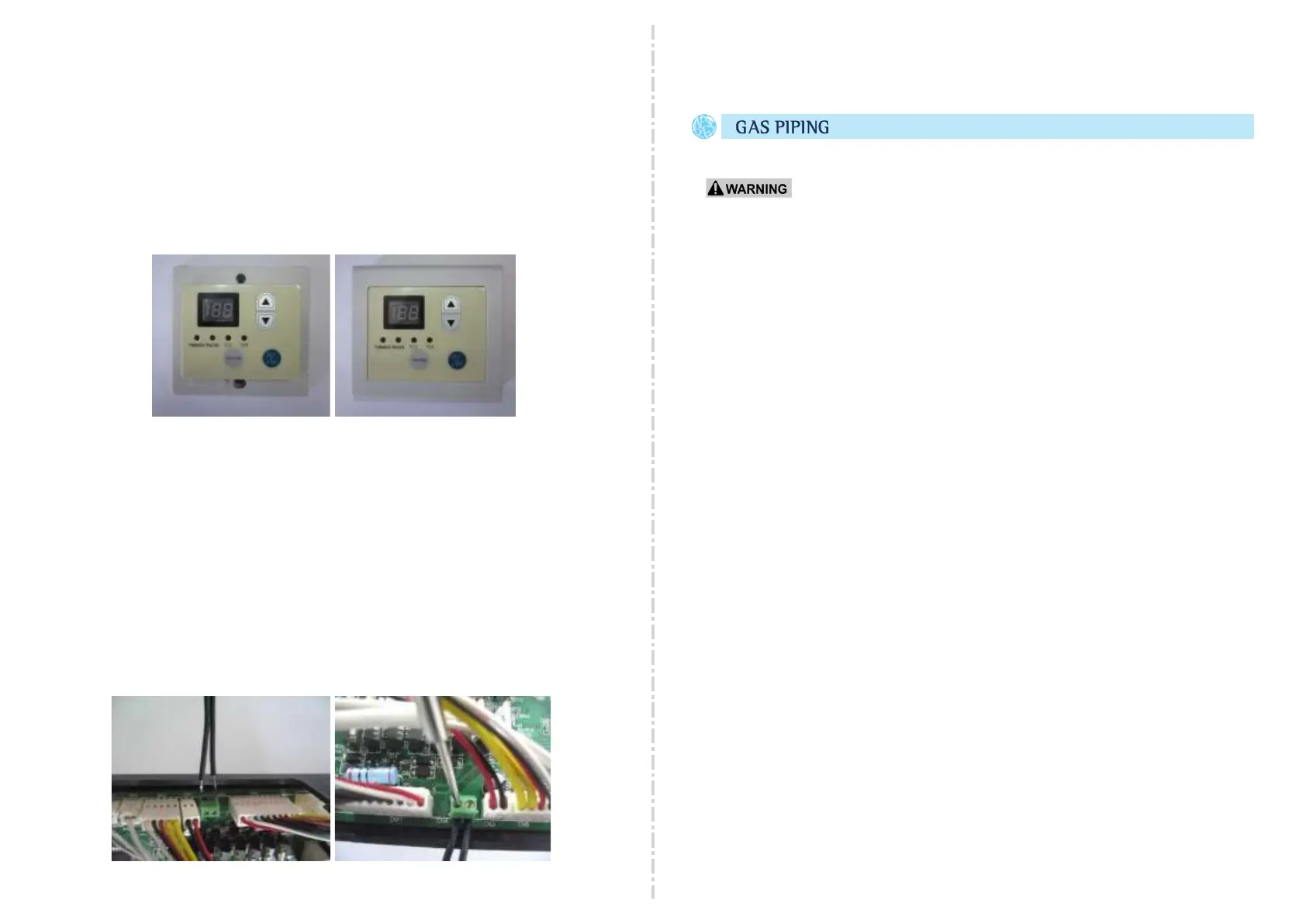
12. Attach remote wires to the UNIT as follows:
1. Remove the front cover of unit.
2. Thread the cable through the access hole and wire bushing at bottom
cover of unit and reinsert the wire bushing into the hole.
3. Remove the PCB and lift out of unit slightly to access wire terminal screws.
4. Insert the wire into terminals ② on PCB controller and tighten using a
screw driver. If using Thermostat Wire proceed to step 5a.
 Loading...