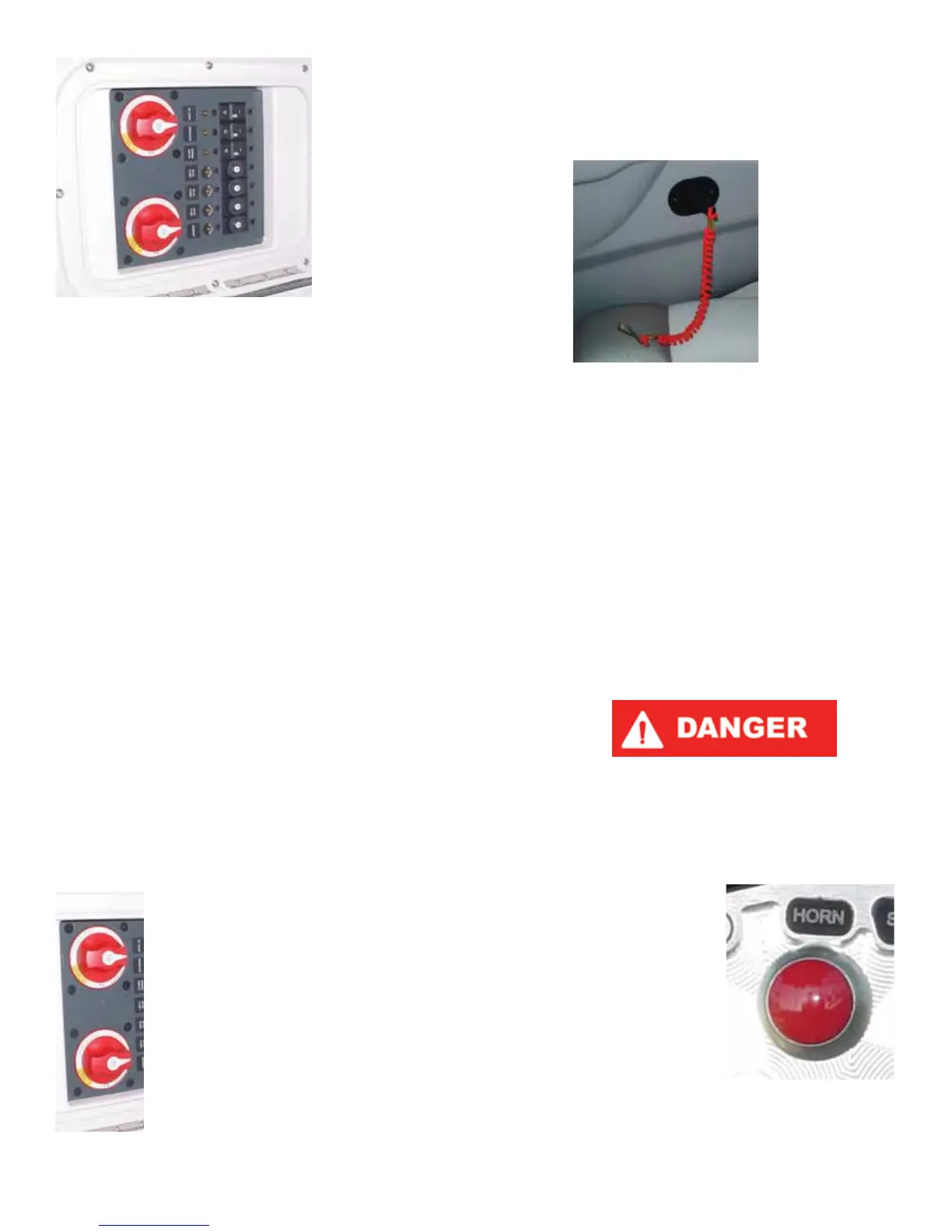
Engine Emergency
Safety Stop Switch
(All Models)
The engine emergency safety stop switch, which
is attached to the lanyard, is an ignition cut-o switch
designed to stop the engine in the event the operator is
thrown or moves too far away from the helm.
The lanyard is equipped with a hook on one end that
should be attached to your clothing or PFD, and the op-
posite end has a slide that ts over the ignition switch.
Be sure that the slide is rmly attached to the ignition
switch before starting.
The ignition switch is located near the throttle con-
trol box, the armrest or on the instrument panel. If the
slide is left o or is loose, the engine will crank but will
not start. Operators should NEVER attempt to over-
ride this safety system!
The safety switch lanyard must be attached to
the operator whenever the engine is running.
Failure to do so may result in death or serious
injury!
Horn
(All Models)
The horn is sounded
by means of a button
on the instrument pan-
el. Pressing the button
emits a loud and recog-
nizable noise.
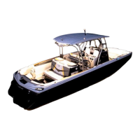
The location of the main circuit
breaker board is under the dash panel.
In some models, there is an additional
breaker panel to assist with the acces-
sory load, and where equipped is lo-
cated near the battery box. There may
also be a waterproof fuse for the stereo
amplier, where equipped. If the boat’s
accessories are malfunctioning, check
and then re-set breakers as necessary.
The engines are also equipped with
breaker systems. The main 35A circuit
breaker protects the engine electrical
system and components from overload.
If the engine will not turn over with the
battery switch in the ON position, lo-
cate the red breaker re-set button (labeled “35”) in the engine. There will be an audible
click. Try again to start the engine. If the breaker trips again, the engine requires atten-
tion. Immediately take your boat to your authorized MasterCraft service department.
In addition to the 35A circuit breaker, the engines are equipped with additional com-
ponent overload protection, including a 15A ATO fuse for the fuel pump, a 15A ATO fuse
for the injectors and a 15A ATO fuse for the ECM unit.
If you suspect that any of these fuses may not be operating as designed, you should
take your boat to your authorized MasterCraft service department for inspection and
repair.
If during maintenance or inspection it becomes necessary to remove or re-position
any of the engine’s wiring or wire harness(es) verify that the wiring has been returned
to its original position and that all harnesses are routed correctly before attempting to
use the boat again. If a wiring clip or retainer breaks, replace it immediately. Wiring is
specically routed to eliminate problems related to engine heat and spray or immersion
in liquids. Electrical problems may result if wiring is moved from its original position!
Dual Battery Operation Switch
(All V Models and Similar X Series, X-Star)
All equipped models except 280 and X-80: For normal operation the battery switch should
be placed in the ON position. This allows the engine and all accessories to receive power.
The engine will recharge both batteries with the switch ON. For transportation and stor-
age, the battery switch should be placed in the OFF position to allow both batteries to
be isolated from all circuits.
Note: The switch knob may be removed when it is in the OFF position. This is a security
feature.
If the engine will not start because the battery is discharged, the engine may be
started from the house battery by placing the switch in the COMBINE BATTERIES posi-
tion. After the engine is started, the switch should be returned to the ON position and
NOT allowed to remain in the COMBINE Batteries mode.
MariStar 280 and X-80: For normal operation the port and starboard
battery switches should be placed in the ON position. The COMBINE
BATTERIES switch should remain OFF. The engine and all accessories
will receive power.
Note: The port battery is a dedicated start battery for the port en-
gine and the starboard battery provides starting current of the star-
board engine while also providing power for accessory circuits. For
transportation and storage, all battery switches should be placed in
the OFF position to isolate both batteries from all circuits.
NOTE: The switch knob may be removed when it is in the OFF position.
This is a security feature.
If either battery becomes discharged, start the engine with the re-
maining charged battery and THEN set the COMBINE BATTERIES
switch to ON. The remaining engine may then be started. Return
the COMBINE BATTERIES switch to OFF. The COMBINE BATTERIES
switch should NOT be left ON.
MasterCraft 2012 Owners Manual • Guide to Individual Models • Page 2-31
 Loading...