55
9.13 INCLINE MOTOR REPLACEMENT - CONTINUED
CHAPTER 9: PART REPLACEMENT GUIDE
FIGURE E FIGURE F
FIGURE G FIGURE H
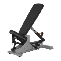
8) Disconnect the wire connection (Figure E).
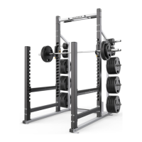
9) Prepare the new motor for installation, the new motor will have the nut placed at the end of the screw shaft – DO NOT move the nut (Figure F).
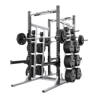
10) Install the new motor using the plastic washers (Figure G).
11) Reverse Step 6 to secure the new incline motor in place, and then reconnect the ground wire from step 2. NOTE: Do not overtighten the pivot
bolt – the incline motor must be able to swivel.
12) Reconnect the power cord and turn the machine on. Follow the procedure in Section 4.8 to calibrate the lift motors. As long as calibration
passes, turn off the power and continue to Step 11.
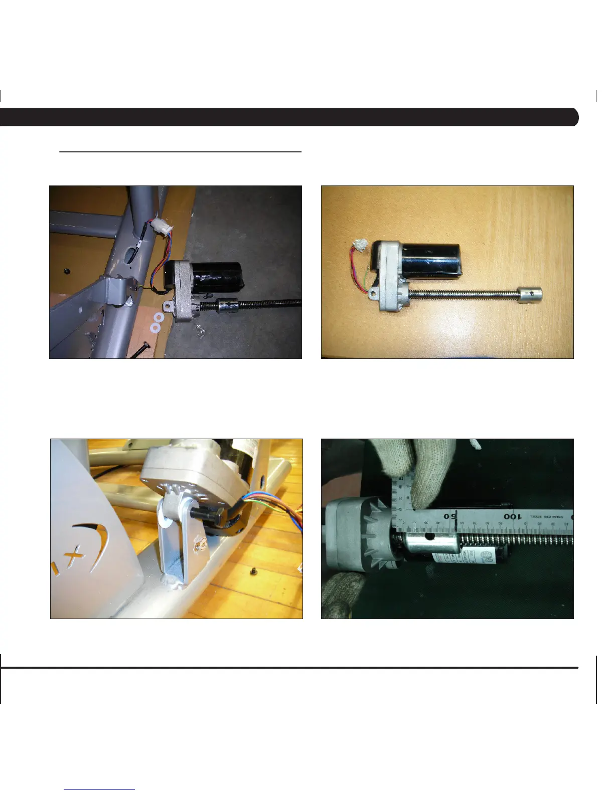
13) Set the nut on the Acme screw to a distance of 67mm from the base of the motor casing to the furthest end of the nut (Figure H).
14) Reattach the swing arm to the nut with 8mm bolts by reversing Step 4.
15) Reinstall the rear shrouds.
16) Test the Ascent Trainer for function as outlined in Section 9.19.
 Loading...