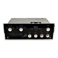
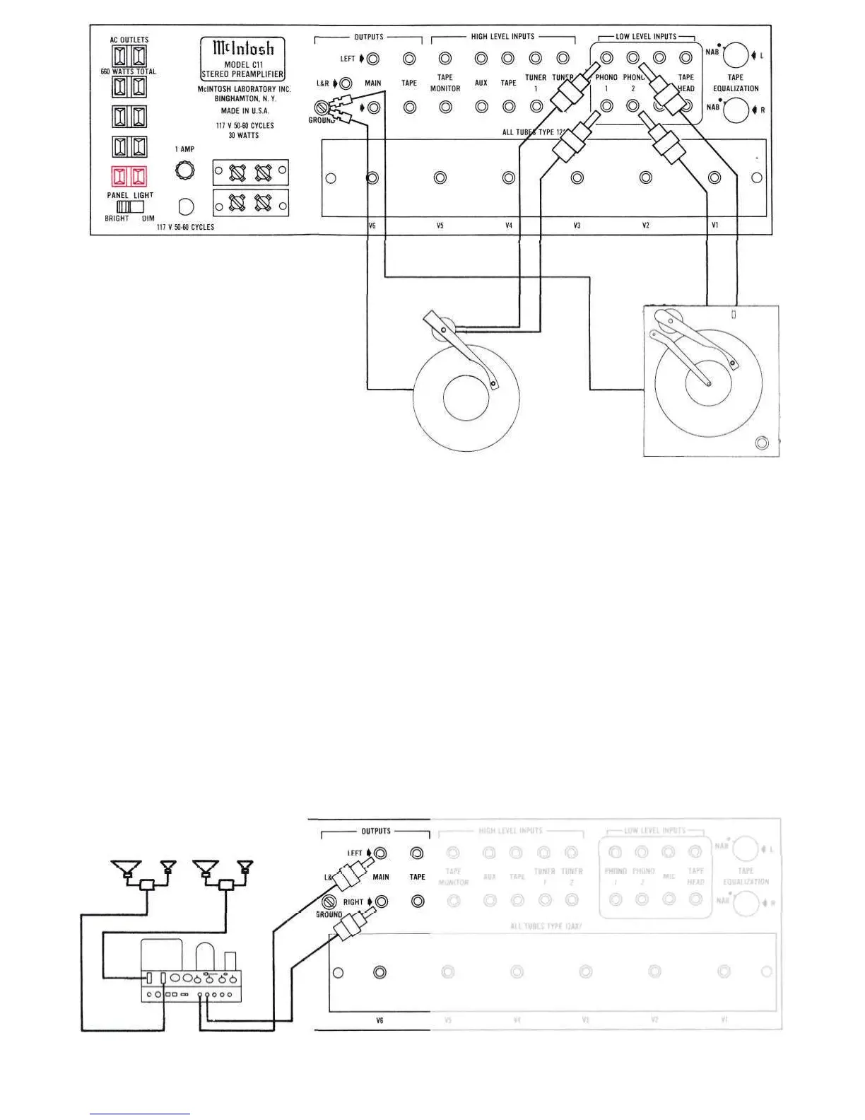
Figure 8. Turntables Feeding Low Level Input
OUTPUT CONNECTIONS
Two sets of outputs, located in the upper
left-hand corner of the back panel, are pro-
vided. (See Figure 2.)
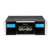
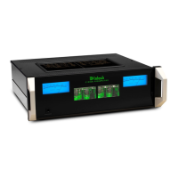
The MAIN output connects to power am-
plifiers (Figure 9) and the TAPE output to
feed a tape recorder.
The MAIN and TAPE output jacks are fed
from cathode followers. The input impedance
of devices connected to these outputs should
be 50,000 ohms or greater, and the capaci-
tive reactance of audio cables connecting
these devices should not be less than 8,000
ohms at 20,000 cycles. This is the reactance
of a capacity of 1,000 mmf. Audio cable
having a capacity of 25 mmf per foot may be
40 feet long; 13.5 mmf per foot cable may be
75 feet long.
The tape output is affected only by the
INPUT SELECTOR in the AUX, TAPE, TUNER
1, TUNER, or MIC positions.
When the INPUT SELECTOR is turned to
PHONO 1 or PHONO 2 inputs then the record
compensator is included. When the INPUT
SELECTOR is turned to TAPE HD then the
record compensator switch should be set at
RIAA.
On the back panel there are two TAPE
EQUALIZATION controls. These controls
should be set to NAB for normal 7.5 inch tape
speed machines. Turning the TAPE EQUAL-
IZATION controls clockwise increases the
Figure 9. MAIN Output Connected to Power Amplifiers
10
 Loading...