HIGH LEVEL INPUTS
These receptacles accept high-level pro-
gram source connections as follows:
TAPE MONITOR (COMPARE) . . . accepts a
signal from a tape recorder with a monitor
head and preamplifier.
AUX . . . accepts any auxiliary service re-
quiring flat frequency response, such as a
T.V. set, tuner, tape recorder with its own
playback preamplifier, etc.
TAPE . . . accepts connection from a tape
machine with its own playback preamplifier.
TUNER 1 & TUNER 2 . . . accept AM and FM
outputs from a stereo tuner or a pair of
stereo tuners.
LOW LEVEL INPUTS
These receptacles accept low-level pro-
gram source connections as follows:
PHONO 1 & 2 . . . accepts connection for
normal stereo and normal monophonic
operation.
MIC . . . accepts connection from stereo
microphones.
TAPE HEAD . . . accepts connection from a
The C11 can be installed in conventional
furniture cabinets, custom built installations
or professional relay racks. If the unit is to
be placed on a shelf or table-top, it is recom-
mended that it be housed in a Mcintosh L66
cabinet. Install the C11 from the front of the
cabinet, not from the rear.
To support the weight of the C11, the
wood panel used to mount it, should be at
least ¼ inch thick. If the front panel of a cabi-
net is made of wood, a shelf may be needed
to support the rear of the chassis to prevent
tape deck that does not contain its own
playback preamplifier.
TAPE EQUALIZATION
On the back panel there are two tape
equalizing controls. These controls should be
set to NAB for normal 7.5 inch tape speed
machines. Turning the TAPE EQUALIZATION
controls clockwise increases the treble re-
sponse, turning it counterclockwise de-
creases the treble response. Use the controls
to compensate for 3% tape speed for indi-
vidual tape head characteristics.
LOUDSPEAKER PHASING CONNECTIONS
Two pairs of screw terminals are located
on the lower left section of the C11 back
panel. The speaker leads from the "left"
power amplifier should be connected to the
screw terminals marked FROM AMPLIFIER.
The pair of terminals marked TO SPEAKER
should be connected to the "left" loud-
speaker.
These connections allow the front panel
PHASE switch to reverse the phase on the
left loudspeaker. This arrangement is con-
venient when setting up a stereo system.
warping. When the C11 is mounted on a
metal rack panel, a shelf is not needed.
The C11 installation should allow 12
inches behind the front panel so that there
is at least 1½ inches for connectors. The de-
sirable width and height are 16½ inches and
5½ inches, respectively, so that sufficient
space is allowed for the circulation of air.
These are inside dimensions. The front panel
mounting space width and height are 16
3
/
8
inches and 5
3
/
8
inches, respectively.
6
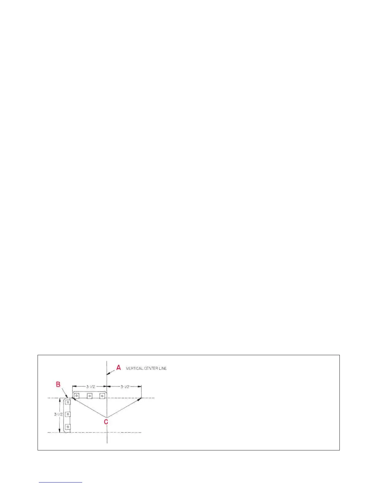
Figure 3. Cutout Measurements
Positions "A" to "C" show the location of the
vertical center line, the use of the measuring
tool (mounting strip) to locate the horizontal
center line, and how to measure off the two
points to the right and left of the vertical
center line.
 Loading...