MAKING THE FRONT PANEL CUTOUT
The panel is cut out using the "FRONT
PANEL CUTOUT TEMPLATE." To position
the template on the front of the panel, make
two locating holes from the back (inside) of
the panel using one of the mounting strips
(½ inch by 3½ inches) as a measuring tool.
Proceed as follows:
Scribe a vertical center line through the
exact center of the proposed cutout area
from the top of the panel to the top surface
of the shelf as illustrated in "A," Figure 3.
Using one of the mounting strips as a meas-
uring tool, draw a horizontal line 3½ inches
above the shelf. (See "B," Figure 3.) Place a
mounting strip along the horizontal line to the
left of the vertical center line and mark a
point 3½ inches left from the vertical center
line. Repeat this procedure and mark a point
3½ inches to the right of the vertical center
line. These points should now be 3½ inches
up from the top of the shelf and 7 inches
apart, one 3½ inches to the left and one
3½ inches to the right of the vertical center
line. (See "C," Figure 3.) Drill a
3
/
16
inch hole
at each point. Hold the drill perpendicular to
the front panel so that the hole will be located
accurately on the front of the panel.
Position the template on the front of the
panel using the two locating holes to line it
up correctly. Scribe the rectangular opening
on the front panel and mark the position of
the six mounting holes. Drill the six
3
/
16
inch
mounting holes before cutting the panel
opening. Then cut out the opening. It is im-
portant that the cutout be just with in the lines.
SHELF MOUNTING
If the installation requires a shelf, proceed
as follows: Locate the center of the shelf and
scribe a line from front to back. The "SHELF
CUTOUT PLATE" is marked for panel thick-
nesses from ¼ inch to 1 inch. Fold the tem-
plate on the line that corresponds to the
thickness of the panel. Place it on the shelf
so that it butts against the inside of the panel.
Match the center line mark on the template
to the scribed center line on the shelf. Mark
the position of the four drill holes. Drill the
four ¼ inch holes.
INSTALLING THE C11
Remove the four screws holding the C11
to the shipping pallet. (Save these screws,
you will need them if your cabinet has a ¼
inch or
3
/
8
inch shelf.) Remove the four plastic
feet from the bottom of the C11.
In the mounting hardware package are
four 6-32 flathead screws and eight 6-32
roundhead screws. Two of the flathead
screws of the proper length are used to at-
tach the mounting strips to the cabinet. Four
of the roundhead screws of the proper length
are used to attach the C11 to the cabinet and
mounting strips. The 6-32 x ½ inch screws
are to be used with panels ½ inch to 1 inch
in thickness.
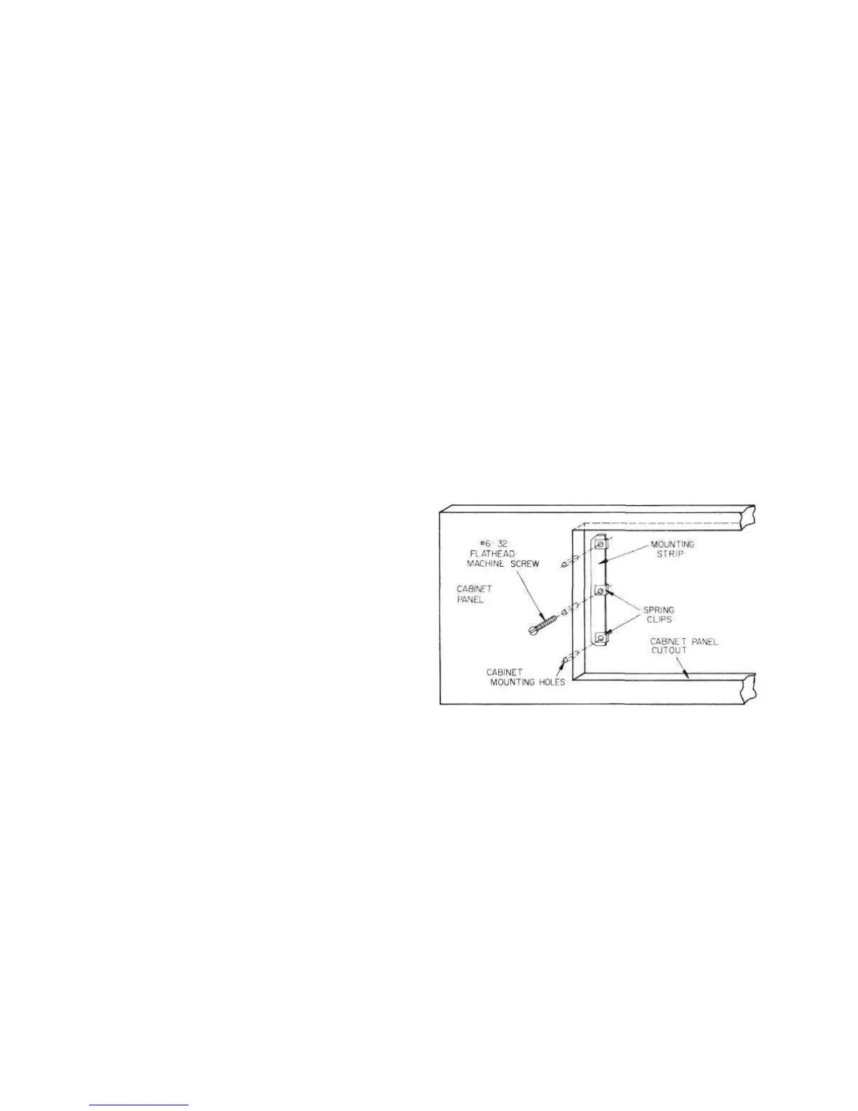
Select the proper length 6-32 flathead
screws and use them to install the two mount-
ing strips behind the front panel. Be sure
that the edge of the strip with the clips is
toward the panel opening. Line up the mount-
ing strips on each side of the front panel
cutout so the three holes in the strip are in
line with the three holes in the panel. (See
Figure 4.) Install the proper length flathead
screws in the center hole of each strip. Drive
them in so the flatheads are flush with the
panel; if necessary, countersink the two
center holes.
Figure 4. Securing the Mounting Strip to the Front Panel
Carefully insert the C11 through the front
of the panel opening so that it rests on the
shelf. Insert the proper length 6-32 round-
head screws into the four holes in the mount-
ing flanges on each end of the tuner front
panel. Drive them in, but do not tighten.
If the cabinet is fixed and will not be
moved about, it is not necessary to secure
the C11 chassis to the shelf. If the cabinet is
to be moved about, it is recommended that
the C11 chassis be secured to the shelf. The
four 10-32 x ½ inch screws used in shipping
are supplied for use if the shelf is under
3
/
8
inch. Use the 10-32 x ¾ inch screws if this
shelf is V2 inch or
5
/
8
inch thick and the 10-32
x 1 inch screws if the shelf is ¾ inch or
7
/
8
7
 Loading...