inch thick. Secure the chassis with the proper
length 10-32 machine screws, inserting them
from beneath the shelf. Do not tighten the
10-32 screws until you have tightened the
front panel screws.
IMPORTANT:
USE OF THE WRONG LENGTH 10-32
SCREWS MAY CAUSE ELECTRICAL
SHORTING IN THE CIRCUIT.
Attach the two metal panel end caps
(packed with mounting hardware) on each
end of the panel by sliding onto the pins.
(See Figure 5.) The end caps are held by
spring tension and can easily be removed if
the chassis is to be taken out of the cabinet.
MOUNTING IN THE L66 CABINET
The Mcintosh L66 cabinet is supplied
with complete instructions and all necessary
hardware for installing the C11. The dimen-
END CAP
PUSH ON
Figure 5. Fitting of Panel End Caps to Panel
sions of the L66 are 16
9
/
16
inches wide by
6
11
/
16
inches high, including mounting feet,
by 13¾ inches deep, including the front
panel and control knobs.
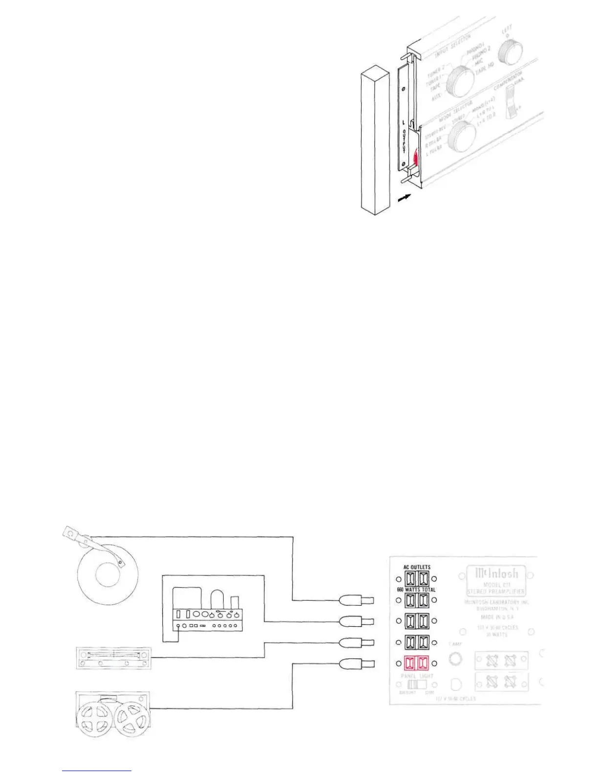
CONNECTING
A-C CONNECTIONS
There are five a-c receptacles on the rear
panel. (See Figure 6.) These receptacles
have a maximum rating of 660-watt total. The
four black receptacles are controlled by the
POWER ON-OFF switch on the front panel.
The red receptacle is not switched. The red
receptacle is used for powering a turntable
or record changer. The receptacle is not
switched so that the turntable power will not
be turned off while the turntable idler wheel
is engaged. The turntable is protected by
this arrangement because it is necessary to
turn off the turntable with its own control
switch so that no damage will result to the
drive system.
Figure 6. A-C Connections
8
 Loading...