VOLUME
VOLUME
This continuously variable control regu-
lates the volume for both channels.
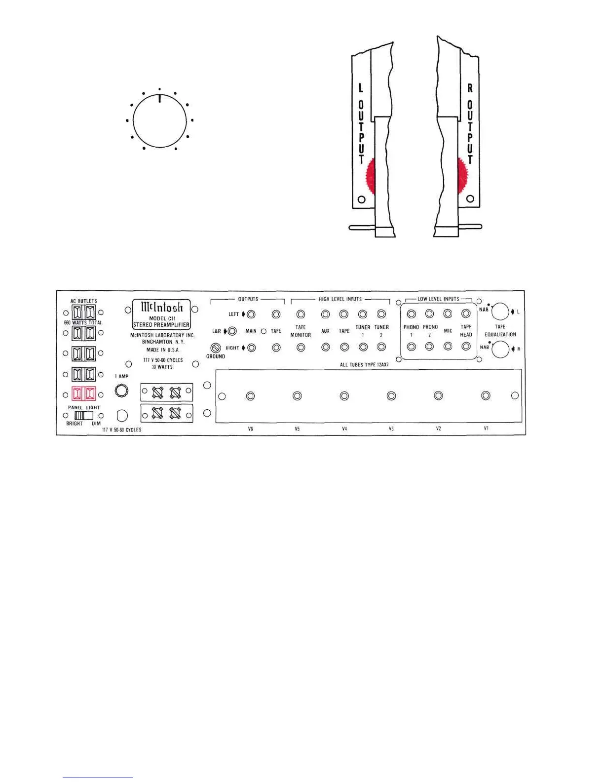
OUTPUT LEVEL CONTROLS
Under the panel end caps are the thumb
wheel OUTPUT LEVEL CONTROLS. The L
OUTPUT is on the left-hand side. The R
OUTPUT is on the right-hand side.
BACK PANEL FACILITIES
Figure 2. C11 Back Panel
AC OUTLETS
There are five AC outlets on the left-hand
side of the rear panel. (See Figure 2.) These
outlets have a maximum rating of 660 watt
total. The four black outlets are controlled by
the POWER ON-OFF switch on the front
panel. The red outlet is used for powering a
turntable or record changer. This outlet is
not switched so that the turntable power will
not be turned off while the turntable idler
wheel is engaged. With this arrangement it is
necessary to turn off the turntable with its
own control switch so that the turntable drive
system will not be damaged.
PANEL LIGHT
The PANEL LIGHT switch, located in the
lower left-hand corner of the back panel,
provides a choice of bright or dim front panel
lighting.
OUTPUT CONNECTIONS
The MAIN output connects to power am-
plifiers (Figure 2); the TAPE output connects
to a tape recorder.
The MAIN and TAPE output jacks are fed
from cathode followers. The input impedance
of devices connected to these outputs should
be 50,000 ohms or greater. The capacitive
reactance of connecting audio cables should
not be less than 8,000 ohms at 20,000
cycles. Longer cables than are normally sup-
plied can be connected between the C11
and the amplifiers or loudspeakers. The
length of the cable is limited by the capacity
of the cable per foot. The total capacity must
not exceed 1000 mmf. For instance; cables
with a capacity of 25 mmf per foot may be
40 feet long; 13.5 mmf per foot cable may be
75 feet long.
5
 Loading...