11
treble response, turning it counterclockwise
decreases the treble response. Use the con-
trols to compensate for 3% tape speed for
individual tape head characteristics.
A left plus right output jack is next to the
MAIN output. It is marked L+R. A mono-
phonic signal can be distributed to other
rooms by connecting a third power amplifier
to the jack marked L+R. This amplifier is
used to drive the monophonic loudspeakers.
The cable connecting to this output should
not have a capacity of more than 200 mmf.
The input impedance of the power amplifier
connecting to this output should not be less
than 150,000 ohms (150K). The generator
impedance at this output is approximately
25,000 ohms (25K).
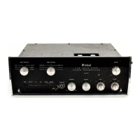
LOUDSPEAKER PHASING CONNECTIONS
Two pairs of screw terminals are located
on the lower left section of the C11 back
panel. The speaker leads from the "left"
power amplifier should be connected to the
screw terminals marked FROM AMPLIFIER.
The pair of terminals marked TO SPEAKER
The ultimate in stereo performance and
listening enjoyment is obtained through the
proper balancing of the stereo system. A
properly balanced stereo system must be in
phase. Each channel must be equal in loud-
ness and similar in frequency response.
Do not use the C11 BALANCE control for
this procedure. The C11 BALANCE control
is used to adjust for any unbalance in the
source material, the phono cartridge, and
tape machine.
Before attempting the balancing of the
C11 make sure the controls on the amplifiers
are set properly. On the MC240 and MC275
turn the control marked BALANCE to its
center position. On the MC225 set the input
level controls for each channel to the black
dot above the control.
To properly balance the C11, proceed as
follows: A familiar recording, either stereo-
phonic or monophonic, should be used in
balancing the C11.
1. Turn the INPUT SELECTOR to the posi-
tion corresponding to the program selected.
2. Turn the BASS CONTROLS and TREBLE
CONTROLS to their 0 positions.
3. Turn the MODE SELECTOR to the L+R
TO L position.
4. Place the COMPENSATOR switch in the
RIAA position.
5. Place the TAPE switch in the NORMAL
position.
6. Place the PHASE switch in the NORMAL
position.
7. Place the POWER switch in the ON
position.
8. Place the RUMBLE switch in the FLAT
position.
9. Place the H.F. cutoff filter switch in the
FLAT position.
10. Place the LOUDNESS switch in the
NORMAL position.
11. Turn the BALANCE control to the 0
position.
12. While the program is playing, alternate
the MODE SELECTOR between the L+R TO
L position and the L+R TO R position. Adjust
the thumb wheel level controls under the
end caps until the loudspeakers are of equal
loudness.
When the proper balancing of the Mcin-
tosh C11 is accomplished, the stereo system
will remain balanced throughout all modes
of operation.
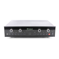
OPERATING INSTRUCTIONS
BALANCING A STEREO SYSTEM
should be connected to the "left" loud-
speaker.
These connections allow the front panel
PHASE switch to reverse the phase on the
left loudspeaker. This arrangement is con-
venient when setting up a stereo system.
GROUND CONNECTION
A single ground post is provided. The
chassis ground from turntable, record chang-
ers (motors used with each), tape decks, etc.,
should be returned to this post. Do not dupli-
cate this ground circuit. Hum is likely to be
heard in the system if duplicate ground re-
turns are used.
The left and right program cables from
each source should be twisted together and
the ground wire from each source can be
wound or twisted in with these cables. To
avoid hum, make sure the ground wire does
not make any connections to shields of the
left and right channel cables except for the
connection provided with the C11 ground
post.
 Loading...