Page 20 IM 781-2
Grounding—Ground Green or bare copper Grounding stud
On 240 VAC models, connect 240 VAC, 50/60 Hz power to the terminals provided using the information in Table 2.
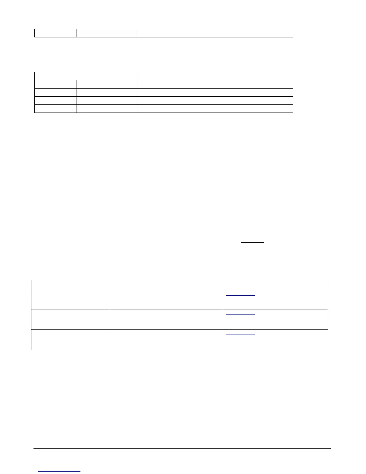
Table 2. International Models - 240 VAC models building power termination
Building Power Source Termination point
Type of Wire Typical Color of Wire
Ungrounded—Hot Brown Either empty terminus of the terminal block
Grounded—Neutral Blue Other empty terminus of the terminal block
Grounding—Ground Green or bare copper Grounding stud
Ethernet Communications to the User Interface and BACnet
A single female 10/100-Mbit Ethernet connection is provided on the controller. See the Main Board Layout (see Figure
29) for location of this connection. Connection is made using a standard male RJ-45 (8-wire) connector. This connection
can be used for multiple PC access to the CSM’s User Interface using a web browser and for connection to a BAS using
BACnet IP or BACnet Ethernet. Since the CSM supports access from multiple devices, the CSM’s Ethernet port is
normally connected to a hub to allow multiple devices connection to the CSM through an Ethernet network. This Ethernet
network is commonly referred to as a local area network (LAN).
Connect one end of a conventional (sometimes called a patch cable) Ethernet cable through the adjacent knockout to the
RJ-45 connector on the CSM. Connect the other end to an Ethernet hub. The maximum end-to-end distance from the
controller to the hub is 328 feet (100 meters). If this hub is connected to a building LAN, the BACnet BAS and the User
Interface may be accessed anywhere on the LAN. If this LAN is connected to the Internet through an IP router, the BAS
and the User Interface may be accessed anywhere in the world if security access through the firewall is granted (see your IT
department regarding access through the firewall from remote locations).
Access to the CSM’s User Interface using a web browser does not require a LAN. Direct connection between a PC and the
CSM by connecting the RJ-45 port on the CSM to the Ethernet port on the PC using a crossover Ethernet cable. Crossover
Ethernet cables are exactly like conventional patch cables (used when connecting through a hub) but if you look at both RJ-
45 connectors, the wire colors leading to the pin locations are “crossed”. If you look at the wire colors leading to the pins
of a conventional patch cable the same color wire goes to the same pin on both RJ-45 connectors.
Table 3. Examples of Possible Ethernet Hardware
Part Description Available at:
Ethernet Patch Cable– for
connection from a hub to the CSM
RJ45 CAT 5 patch cable (straight through, not
crossover). Other lengths may be substituted based on
job site requirements.
www.cdw.com - CDW # 073963 (7 feet) or CDW
# 074118 (25 feet) or CDW # 088310 (100 feet)
Ethernet Cross-over Cable – for
direct connection from a PC to the
CSM
RJ45 CAT 5 crossover cable (wires are crossed-over,
not straight through). Other lengths may be
substituted based on job site requirements.
www.cdw.com - CDW # 216593 (7 feet) or CDW
# 379326 (25 feet)
Ethernet Hub – only required if a
existing LAN hub is not available
10/100BASE-TX Fast Ethernet hub www.cdw.com - CDW # 138572 (5 ports)
LONWORKS Communications to Chillers and Remote I/O Modules
All communications between the CSM, chillers, and remote I/O modules is provided via LONWORKS communications
network. The CSM and all associated devices use the FTT-10A Free Topology Twisted Pair Transceiver, which allows for
simple, flexible network wiring.
A dedicated L
ONWORKS loop is required due to network management considerations. Since the CSM is a LONWORKS
network management device, connecting another LONWORKS network management device to any device in the CSM
network will undo the CSM’s commissioning of that device. If this happens, that device must be re-commissioned to the
CSM.
 Loading...


