IM 781-2 Page 53
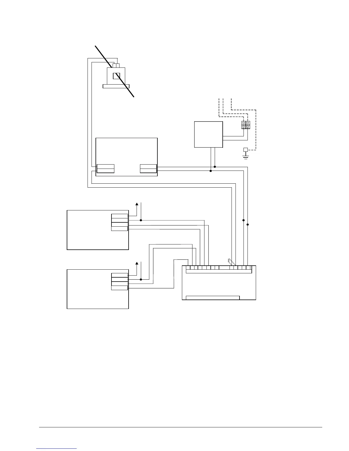
Figure 33. Hardwired Chiller’s Possible Hardware Requirements
Transformer
40 VA
24 VAC Secondary
Ground
Primary
Primary Power Supply
3
Hardwired Chiller’s
Remote I/O Module
4
10 VA
Low Voltage Terminals-Brown
High Voltage Terminals-Orange
11 10 2 1
SIG OUT
COM
24V PWR
SIG IN
0-10 VDC to 4-20 mA
Converter for Chilled Water
Temperature Reset
10 VDC
4-20 mA to
Chiller Setpoint
Reset AI
Signal Converter
2.5 VA
10 VDC
4-20 mA to Chiller
Demand Limit AI
SIG OUT
COM
24V PWR
SIG IN
0-10 VDC to 4-20 mA
Converter for Load Limiting
Signal Converter
2
2.5 VA
24
dc Power Supply
1
15 VA
24 VDC Out +
24 VDC Out -
24 VAC In G
24 VAC In H
Current Transducer Mounted on Chiller
1
(4-20 mA Output)
Range
0-300 Amps
0-800 Amps
0-2400 Amps
+ -
499
Ω
Res
Notes:
1. Current Transducer and 24 VDC Power Supply required if chiller does not output a %RLA signal (0-10 VDC or 4-20 mA) directly.
2. Signal Converter required if chiller does not accept 2-10 VDC signals at it’s analog inputs.
3. Power supply must provide electrical isolation between inputs and outputs.
4. McQuay remote I/O panel provides 40VA-24VAC transformer and is available with up to four remote I/O modules. See IM 783-
MicroTech II Remote I/O Panel Installation Manual for more information. Verify dimensions of the remote I/O panel for clearance
and follow appropriate electrical codes.
35 34 33 32 31 30
 Loading...


