Page 8 IM 781-2
Applying the CSM
The CSM has been designed to control several common chiller plant configurations. Figure 2 shows a typical chilled water
system configuration. The following pages describe typical plant configurations that can be controller by the CSM and the
guidelines for applying the CSM in them. The chillers in these configurations can be all centrifugal, all reciprocating, all
screw, or a combination of centrifugal, reciprocating, or screw.
The CSM may be suitable for applications other than those shown. If your application does not match one of the listed
configurations, contact your McQuay sales representative for assistance.
Typical Chilled Water System
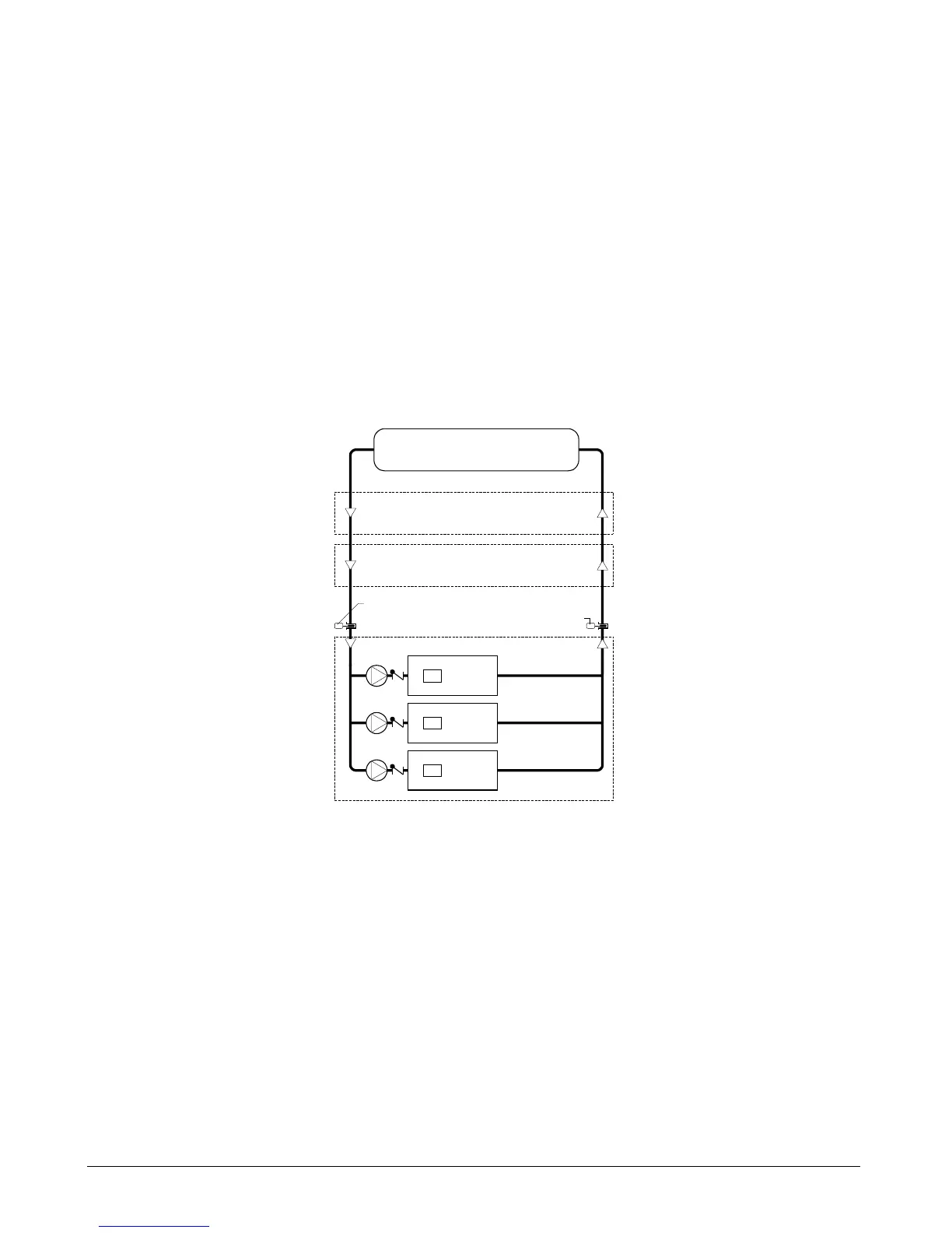
The typical chilled water system configuration is shown in Figure 2. The characteristics of this system consist of the
following: (1) a set of chillers, usually piped in parallel, (2) each chiller has its own primary chilled water pump, (3) the
system may or may not have a bypass line and valve that is controlled by a differential pressure controller, (4) the system
may have secondary pump(s) to distribute water to the cooling loads.
Figure 2. Typical Chilled Water System
Cooling Loads
Chiller #3
centrifugal
C
Chiller #2
centrifugal
C
Chiller #1
centrifugal
C
Chiller evaporator configuration
Loop bypass configuration
Return chilled water temperature
Supply chilled water temperature
Secondary pump/decoupler line configuration
a0093
Variations to the typical chiller system configuration can be controlled. Refer to Figure 3 through Figure 11. The options
described by inserting these figures into the dotted areas shown in Figure 2 above can also be controlled by the CSM.
Chiller Evaporator Configuration
In these systems (Figure 3 through Figure 6), the temperature of the water entering the loads will always be very close to
each chiller’s leaving evaporator water temperature setpoint. In Figure 6, all chillers share a common primary pump but
each chiller has an isolation valve.
 Loading...


