Page 46 IM 781-2
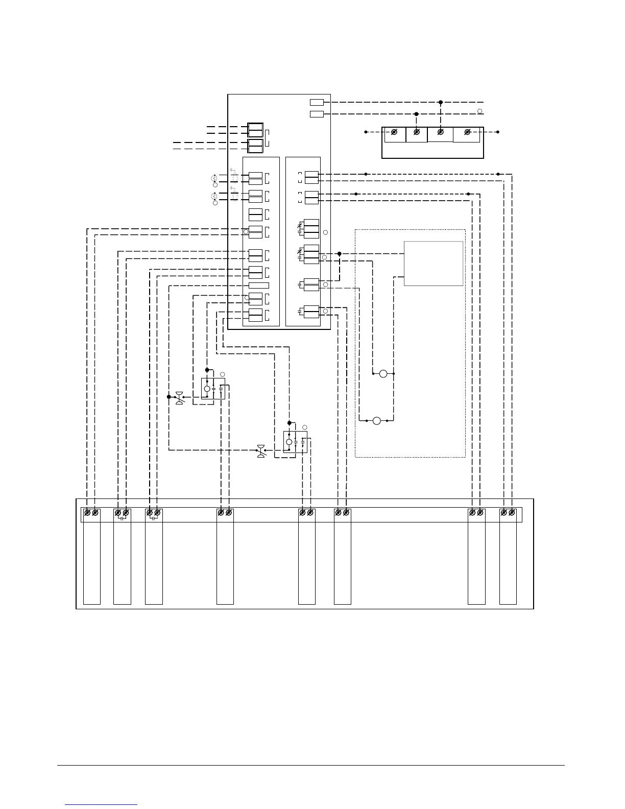
Figure 30. Typical Hardwired Chiller Field Wiring Diagram
Remote I/O Module
Inputs
Lon Port
Evaporator Pump Relay
(By Others)
Outputs
NC 57
Com56
NO 58
NC 54
Com53
NO 55
Com49
NO 50
Com47
NO 48
Relay 5
Relay 4
Relay 2
Relay 1
4
3
35 (Y)
34 (0)
AO 2
32 (Y)
31 (0)
AO 1
Notes:
1. Do not ground the common side of the power supply transformer to maintain analog signal isolation from ground.
2. Temperature sensor must be 20k NTC (thermistor).
3. 499 ohm resistor required across AI terminals with 4-20mA signal input. No resistor required if 0-10V input.
4. Normally Open contacts on remote I/O module rated for 6 amps at 230 volts.
5. Double throw relay with 24 VAC coil.
6. If the chiller controls its own condenser pump or the chiller is air-cooled, a jumper must be placed across DI 2.
2-10VDC
2-10VDC
Hardwired Chiller
In from Lon Network of CSM, Lon Chillers
and/or other Remote I/O Modules
25
24
Out to Lon Network of Lon Chillers
and/or other Remote I/O Modules
20 (Y)
19 (0)
17 (Y)
16 (0)
AI 4
AI 3
Chiller Leaving Condenser Water Temperature
(Optional)
Chiller Leaving Evaporator Water Temperature
(Optional)
2
2
8 (Y)
7 (0)
DI 2
6 (Y)
5 (0)
DI 1
Chiller Unit Controller
Remote Auto/Stop Input
14 (Y)
13 (0)
AI 2
11 (Y)
10 (0)
AI 1
3
Demand Limit Input
(2-10VDC or 4-20mA)
Chilled Water Setpoint Input
(2-10VDC or 4-20mA)
- +
Splice Splice
Splice in a signal converter if chiller requires 4-20mA
Splice Splice
Splice in a signal converter if chiller requires 4-20mA
2 (0)
1 (
~
)
20mA Sig Out
Voltage to Current Converters
(used if chiller requires 4-20mA input signal)
Splice
Splice
10V Sig In Common 24VAC PWR
24 VAC power 50/60 Hz
1
27 (Y)
26 (0)
DI 3
29 (Y)
28 (0)
DI 4
- +
115V or 220V or 24V
50/60 Hz
(By Others)
N
4
4
%RLA Output (if %RLA is
not available, measure amps)
+ -
EPR
Condenser Pump Relay
(By Others)
Water Cooled Chillers Only
CPR
Alarm Signal Output
(dry contact)
9 (24Vac)
Condenser Water Flow Input
Cond Water
Flow Switch and
Relay
(By Others)
Water Cooled
Chillers Only
Evaporator Water Flow Input
Evap Water
Flow Switch
and Relay
(By Others)
5
5
If Pumps Are Controlled By Chiller Unit
Controller, Disregard This Section
Second Alarm Signal Output
(optional on multi-comp units)
4
4
Spare
6
CD 251740501
 Loading...


