Page 24 IM 781-2
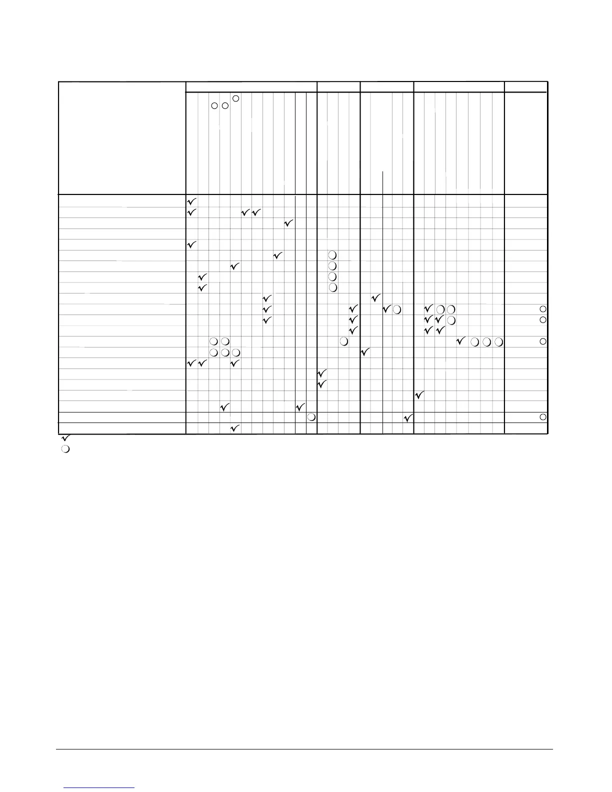
Table 4. Analog/Digital Inputs and Outputs
Input or output required
Input or output optional
Notes:
1. Cooling tower staging and cooling tower bypass valve control require either a leaving condenser water temperature sensor or an entering condenser water temperature. If constan
approach setpoint reset will be used requires the control temperature to be the entering condenser water temperature.
2. The CSM can also get the outdoor air temperature from a chiller (if chiller has OAT sensor) or a building automation system.
Analog Input
CSM Feature
11
2
Standard chiller se
uencin
control
Decoupled chiller sequencing control
External Demand limiting
Unit leaving chilled water control
Common lvg. chilled water control
External reset
Outdoor air temperature reset
Return ChW temperature reset
Constant return ChW temp. control
ChW loop bypass valve control
Cooling load pump control: VFD
Cooling load pump cntrl: Sequenced
Cooling load pump cntrl:
Lead/standby
Cooling tower staging control
Cooling tower bypass valve control
Optimal start
Manual schedule override
External timeclock scheduling
Remote alarm indication
Common ChW Supply Temp
Common ChW Return Temp
Leaving CndW Temp
Entering CndW Temp
Outdoor Air Temperature
Decoupler Line Temp
Flow Meter
ChW Loop Differential Press
Ext ChW Reset Signal
Ext Demand Limiting Signal
Relative Humidity
Tower constant approach reset
Tower fan variable speed control
Digital OutputAnalog OutputDigital Input
External Start/Stop
ChW Reset Override
Cooling Tower Alarm
Pump 1- 6 Status
Cooling Tower Bypass Valve
ChW Loop Bypass Valve
Pump VFD 1
Pump VFD 2 - 6
Alarm Output
Cooling Load Pump 1
Cooling Load Pump 2
Cooling Load Pump 3 - 6
Cooling Tower Outputs 1-4
Cooling Tower VFD 1 - 7
Tower VFD’s Act. Speed 1-16
Low Ambient Lockout
Cooling Tower Outputs 5-8
Cooling Tower Outputs 9-12
Cooling Tower Outputs 13-16
Inputs and
Outputs
Located on
Remote I/O
Module
A, B, C
E, F, G, H
D
A, B, C
E
E, F, G, H
3. Remote module A controls up to two pumps, add remote module B to control up to four pumps, add remote module C to control up to six pumps.
4. The number of remote I/O modules required is dependent on the quantity of cooling tower outputs needed. Each module provides four relay outputs.
4
5
5. Remote I/O module E provides one analog output for tower fan VFD control. Modules F, G, and H provide two analog outputs each for tower fan VFD control.
3
3
Onboard I/O Wiring
The CSM is equipped with an onboard I/O panel inside its cabinet with 16 universal inputs, 8 digital outputs, and a 20-Volt
DC (at 80 mA) power supply. The onboard I/O is connected to the main control board with a ribbon cable. Power is
supplied to the onboard I/O through the ribbon cable from the main control board.
Inputs
External sensors can be wired to the universal inputs of the onboard I/O panel, which supply information from the chiller
system. The CSM’s onboard universal inputs have been configured in the following manner:
a)
UI 1 through 6 = Temperature. Type 3 (10K) Thermistor, -10° to 135°F (-23.3 to 57.2°C) range.
b)
UI 7 through 12 = 0-10 VDC or 4-20 mA. Uses an external resistor for current input (four provided). Self powered
or board powered sensors accepted.
 Loading...


