18 IM710
Humidity Sensors
When the MicroTech II controller is configured for constant
volume zone temperature control (SCC), a dehumidification
sequence is available and can be activated through the key-
pad. In order to use this function, an optional factory sup-
plied, field mounted humidity sensor is required.
Either a wall mount or duct mount sensor is available. The
sensor must be wired to terminals 126, 127 and 131 on the
unit field terminal block (TB2). Terminal 126 is wired to
OUT (0-5 VDC), terminal 127 to GND and terminal 131 to
PWR on the humidity sensor. These terminals are factory
wired to the MCB analog input MCB-AI16. The input must
be 0-5 VDC as the relative humidity varies from 0-100%.
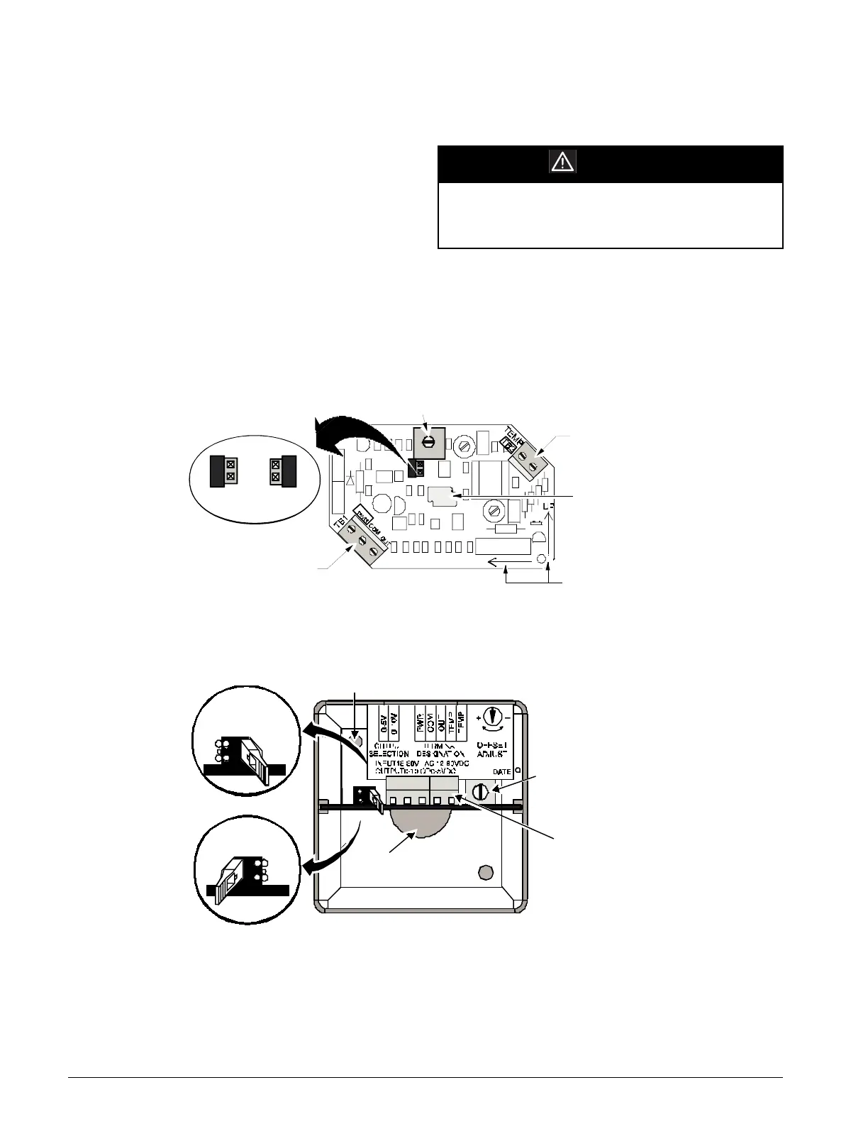
Note: The output select jumper (J1) on the sensor must be
in the 0-5 VDC position. The TEMP terminals on
the sensor are not used (refer to Figure 8).
The humidity sensor wiring to terminals 126 and 127 must
be field-wired to the unit using a twisted pair, shielded cable
(Belden 8761 or equivalent). Cable with 22 AWG conduc-
tors is sufficient.
Note: The analog input jumper associated with MCB-
AI16 must be set to the no jumper (NJ-VDC) posi-
tion. The analog input dip switch associated with
this input must be set to the ON (V) position.
Figure 8: Humidity Sensors (Wall Mount)
Figure 9: Humidity Sensor (Duct Mount)
Humidity Sensor - Discharge Air Control (DAC) Unit
A humidity sensor can be wired to terminals 126, 127 and
131 on TB2 on a discharge air control (DAC) unit. However,
this input is not used for control purposes and the current rel-
ative humidity value from the sensor cannot be read via the
keypad/display. The current value from the sensor can be
read only via a network interface.
CAUTION
Do not install this cable in the same conduit as
AC power wiring. Induced current and RFI from
AC wiring can interfere with the controls.
Output Adjustment
Jumper
0 to 5V
0 to 10V
Terminal Block TB1
Output Adjustment
Potentiometer
Output Adjust
Up
Terminal Block TB2
Wiring Opening
Mounting
Direction
Arrows
Screw Hole
Offset
Adjustment
Potentiometer
Wiring Block
Screw Terminals
are accessed
through the cutout
in the housing
Prone
Screw Hole
0-10V
Output Jumper
(Factory Seal)
0-5V
Output Jumper

 Loading...


