IM710 23
Binary Inputs-Main Control Board (MCB)
The 16 binary inputs to the MCB are in the form of 0 VAC
(off) or 24 VAC (on) applied to the binary input terminals.
Transformer T2 is the source of the 24 VAC for these inputs.
Each binary input has an LED associated with it that lights
when 24 VAC is present at the corresponding input terminal.
These binary input LEDs are grouped together and are
located in the upper left hand corner of the board. Table 10
summarizes the binary input functions and LED indications
for the binary inputs to the MCB.
Binary Inputs-Auxiliary Control Boards
(CCB1 and CCB2)
The optional auxiliary control boards include 12 binary
inputs. Inputs BI1 through BI6 are designed for a set of dry
contacts between the COM terminal and the individual
binary input terminals on J9. BI7 through BI12 are designed
for 24 VAC inputs (input is ON when 24 VAC is present at
the corresponding input terminal on J10 and OFF when
0 VAC is not present). The following sections describe how
these inputs are defined for each of the auxiliary control
boards.
Note: The set of jumpers in the upper right corner of the
board (under the N2 Communications Card) must
both be in the “down” position (jumper on the bot-
tom two pins). Placing the jumper in the “up” posi-
tion (jumper on the top two pins) internally
interlocks binary inputs BO1 with BI1 and BO2
with BI2 respectively. This interlock is not used on
this product application
CCB1 & CCB2
Cooling Circuit #1 through Circuit #4 are controlled by the
CCB1 and circuit #5 and #6 are controlled by the CCB2.
Table 11 and Table 12 on page 24 summarize the binary
inputs for the CCB1 and CCB2 respectively.
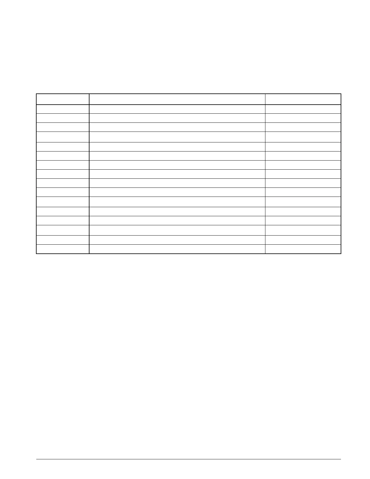
Table 10: Binary Inputs for Main Control Board (MCB)
Binary Input Input Description Lit LED Indication
MCB-BI1 External Time Clock or Tenant Override Occupied
MCB-BI2 Manual System Disable Disabled
MCB-BI3 Remote Cool Enable Enabled
MCB-BI4
Remote Heat Enable
Enabled
MCB-BI5 Heat Failure Alarm Alarm
MCB-BI6 Airflow Status Airflow Detected
MCB-BI7 Freeze Alarm for Steam, Hot Water Coils, or Waterside Economizer Normal
MCB-BI8 Smoke Alarm Normal
MCB-BI9 Filter Switch Normal
MCB-BI10 Not Used -
MCB-BI11
Outdoor Enthalpy Status
a
Low OA Enthalpy
MCB-BI12 Not Used -
MCB-BI13 Not Used -
MCB-BI14
Duct Hi Limit
b
Normal
MCB-BI15 Not Used -
MCB-BI16 Water Flow Switch Normal
a. Not used on 100% outdoor air units.
b. Applicable on VAV units only.

 Loading...


