IM710 19
Field Binary Input Signals
The following sections describe options that, if used, require
field wiring to binary input terminals. Twisted pair, shielded
cable is not required for binary input wiring.
Manual Cooling and Heating Enable
Cooling Enable
24 VAC must be applied to binary input MCB-BI3 to enable
cooling operation. If not, the unit Clg Status= parameter in
the System menu of the keypad/display indicates “Off Sw”
and cooling operation is unavailable. 24 VAC is applied to
MCB-BI3 when terminals 101 and 105 on the unit terminal
block (TB2) are made; either with a factory installed jumper
wire or a field supplied switch. Refer to the unit wiring dia-
grams or Figure 14 on page 34 (DAC units) or Figure 15 on
page 35 (SCC units) for wiring termination details.
Heating Enable
24 VAC must be applied to binary input MCB-BI4 to enable
heating operation. If not, the Htg Status= parameter in the
System menu of the keypad/display indicates “Off Sw” and
heating operation is unavailable. 24 VAC is applied to MCB-
BI4 when terminals 101 and 106 on the terminal block (TB2)
are made; either with a factory installed jumper wire or field
supplied switch. Refer to the unit wiring diagrams or
Figure 14 on page 34 (DAC units) or Figure 15 on page 35
(SCC units) for wiring termination details.
Manual Unit Enable
Unit operation is manually disabled when 24 VAC is applied
to binary input MCB-BI2. The UnitStatus= parameter in the
System menu of the keypad/display indicates “Off Sw” and
the unit will not operate. This occurs when a field supplied
and installed switch across terminals 101 and 104 on the ter-
minal block (TB2) is in the on or closed position. Refer to
the unit wiring diagrams or Figure 14 on page 34 (DAC
units) or Figure 15 on page 35 (SCC units) for wiring termi-
nation details.
If not disabled by this method, the unit is enabled to run
when placed in the occupied mode. For details regarding
occupied/unoccupied operation refer to the “Auto/Manual
Operation” section of the appropriate program-specific oper-
ation manual (refer to Table 1 on page 3).
External Time Clock or Tenant Override
There are several methods of switching the vertical self-con-
tained unit between occupied and unoccupied operation. It
can be done by the controller internal schedule, a network
schedule, an external time clock, or a tenant override switch.
If the internal schedule or a network schedule is used, field
wiring is not required.
An external time clock or a tenant override switch can be
used by installing a set of dry contacts across terminals 101
and 102 on the terminal block (TB2). When these contacts
close, 24 VAC is applied to binary input MCB-BI1, overrid-
ing any internal or network schedule and placing the unit
into occupied operation (provided the unit is not manually
disabled). When the contacts open (24 VAC is removed from
MCB-BI1) the unit acts according to the controller internal
time schedule or a network schedule. Refer to the unit wiring
diagrams or Figure 14 on page 34 (DAC units) or Figure 15
on page 35 (SCC units) for wiring termination details.
For information on setting internal and network controller
schedules, refer to the “Scheduling” section in the applicable
operation manual (refer to Figure 1 on page 5).
Miscellaneous Output Signals
The five optional output signals listed below can be provided
by installing field supplied 24 VAC relays wired between
terminal 107 on the terminal block (TB2) and the terminals
listed in Table 6. Refer to the unit wiring diagrams or
Figure 14 on page 34 (DAC units) or Figure 15 on page 35
(SCC units) for wiring termination details.
●
Airflow status
●
Dirty filter
●
Heat fail alarm
●
Freeze alarm (steam or water coils, optional)
●
Smoke alarm (optional)
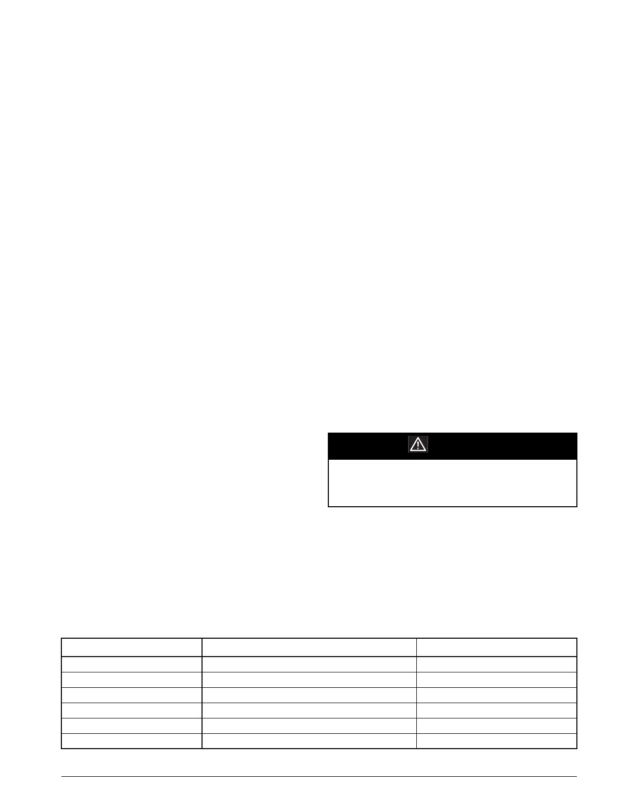
CAUTION
The total VA of all field-mounted relays cannot
exceed 15 VA and they must have a 24 VAC
Class 2 coil.
Table 6: Miscellaneous Field Signal Termination Points
Terminal Block TB2 Description Energized Field Relay Indication
107 Ground NA
108 Fan Operation (Airflow Indication) Airflow Present
109 Dirty Filter Indication Filters Dirty
111 Heat Alarm Detected Alarm
112 Freezestat (Freeze Condition Detected) Normal
113 Smoke (Smoke Detected) Normal

 Loading...


