6 IM710
Main Control Board (MCB)
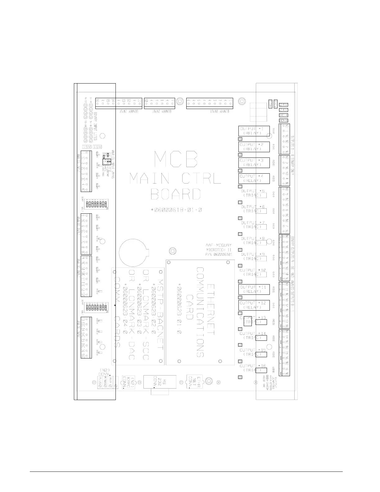
Figure 2 shows the main control board (MCB). It contains a
microprocessor that is programmed with the main applica-
tion code to control the unit. The MCB receives up to 16
analog and 16 binary inputs directly and up to 6 analog and
12 binary inputs from each optional auxiliary control board
(CCB1, CCB2). Auxiliary control boards communicate this
data with the MCB via a N2 communication bus interface.
The MCB controls its own 16 binary outputs and up to 9
binary outputs on each auxiliary board based on the inputs.
Figure 2: Main Control Board
Analog Inputs Terminal Blocks
The MCB receives up to 16 analog input signals on 4 termi-
nal blocks located on the left side of the board. From top to
bottom, analog inputs AI1 through AI4 are terminated on the
first terminal block, AI5 through AI8 on the second, AI9
through AI12 on the third, and AI13 through AI16 on the
fourth. Each analog input has two terminals. The terminals
for AI1 are 1 and 1C, the terminals for AI2 are 2 and 2C, and
so forth. Refer to “Analog Inputs-Main Control Board
(MCB)” on page 20 for details regarding analog inputs.

 Loading...


