50 IM710
Troubleshooting Refrigerant Pressure
Transducers
The following procedure can be used to troubleshoot a sus-
pect sensor:
1. Verify the 5VDC-power supply to the sensors at termi-
nal block TB2 terminals 54 and 55.
a. If the suspect sensor is PSR1, verify that there is
5VDC between wire 179 (RED) and wire 178 (BLK).
b. If the suspect sensor is PSR2, verify that there is
5VDC between wire 279 (RED) and wire 278 (BLK).
2. Measure the DC voltage output from the sensor.
a. If the suspect sensor is PSR1 (MCB-AI11), measure
between wire 177 (WHT) and wire 178 (BLK). MCB-
AI11 should not have a jumper and the dip switch
SW4:3 should be in the ON position.
b. If the suspect sensor is PSR2 (MCB-AI12), measure
between wire 277 (WHT) and wire 278 (BLK).
MCB-AI12 should not have a jumper and the dip
switch SW4:4 should be in the ON position
If the measured voltage and pressure do not match, there
may be a wiring problem or the transducer may be
defective. Check the transducer wiring harness for
defects.
If the measured voltage and pressure match, the MCB
may be defective.
3. Remove power from the controller. If available, swap a
similar good transducer with the suspect transducer or
try installing a new transducer. Restore power and ver-
ify whether the suspect transducer is defective.
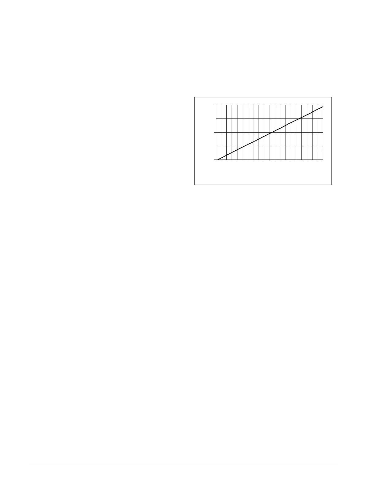
Figure 26: Refrigerant Pressure Transducer Voltage vs.
Pressure
1
2
3
50 100 150 200 250
Refrigerant Pressure (PSIG)
Sensor Output (VDC)

 Loading...


