IM710 33
Typical Wiring Diagrams
The following vertical self-contained unit wiring diagrams
are typical. They are included here to show common factory
and field wiring schemes. For exact wiring information per-
taining to a particular unit, refer to the wiring diagrams sup-
plied with the unit.
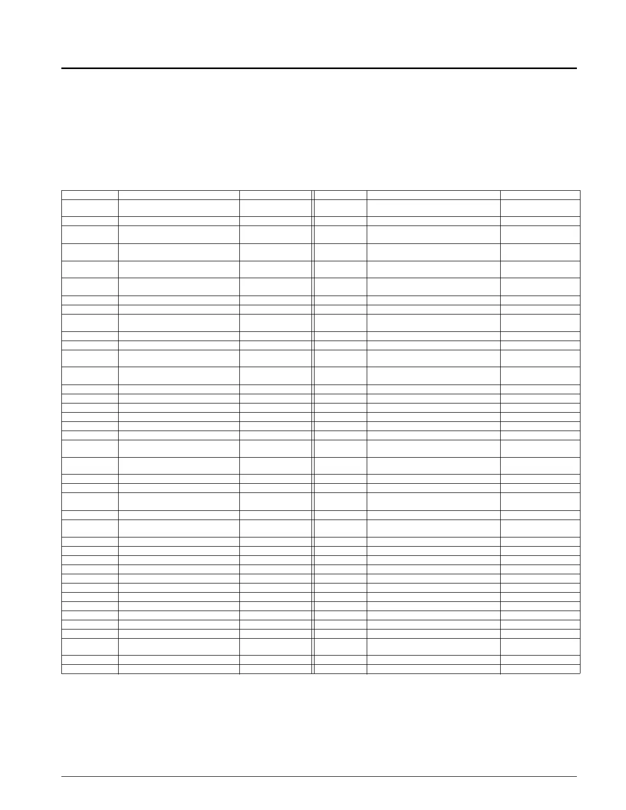
Note: Some of the component designations depend on
unit sizes. The abridged legend shown in Figure 13
applies to Figure 14 through Figure 20. For com-
plete, exact component designations and locations,
refer to the legend supplied with the unit.
Figure 13: Electrical Schematic Legend
Designation Description Standard Location Designation Description Standard Location
ACT1 Actuator,Variable Inlet Vanes
Supply Fan Sec-
tion
OAE Outside Air Enthalpy External
ACT2 Actuator,Bypass Valve Condenser Valve OAT Outside Air Temp. Sensor External
ACT3 Actuator,Waterside Economizer
Waterside Econo
Valve
OL10 Overload Relay--Supply Fan Main Control
AFD10
Adjust.Frequency Drive--Supply
Fan
Main Control PB1
Power Block--Total Unit Or
Compr/Heat
Main Control
CCB1,2
Compr Control Boards--Refrig.
Circuits
Main Control PB2 Power Block--Saf/Raf/Controls Main Control
COMPR#1-6 Compressors #1--6
Compressor Sec-
tion
PC5 Pressure Control--Clogged Filter Supply Air Section
DAT Discharge Air Temp. Sensor Near Fan Inlet PC7 Pressure Control--Proof Airflow Supply Air Section
DHL Duct Hi-Limit Main Control PM1 Phone Modem Main Control
DS1
Disconnect--Total Unit Or
Cond/Heat
Main Control PSR1,2 Pressure Sensor,Refrigerant Liq. Shutoff Valves
DS2 Disconnect--Saf/Raf/Controls Main Control PVM1 Phase Voltage Monitor Main Control
EWT Ent. Cond. Water Sensor Cond. Water Inlet PVM2 Phase Voltage Monitor Main Control
F1 Fuse--Control Circuit Main Control R11
Relay--Electric Heat Stage 1 Hw/S
Close
Main Control
FB10 Fuseblock--Supply Fan Main Control R12
Relay--Electric Heat Stage 2 Hw/S
Open
Main Control
FB11,12 Fuseblocks--Electric Heat Main Control R1-6 Relays--Hi-Pressure Main Control
FB1--6 Fuseblocks--Compressor #1-6 Main Control R18 Relay--Cool Enable Main Control
FB8 Fuseblock--Main Transformer Main Control R67 Relay--Enable Supply Fan Main Control
FP1-6 Frost Protection--Refrig. Circuits Evap. Coil RAE Return Air Enthalpy External
FS1 Freezestat Control Bt/Dt Coil RAT Return Air Temp. Sensor External
GRD Ground All Control Box S1 Switch--System On/Off Main Control
HL13-14 Hi-Limits, Pwr, Elec Heaters
Electric Heat
Jct.Box
S4,5 Switches--Inverter Bypass Main Control
HP1-6 Hi-Pressure Controls, Refrig
On Compressors
#1-6
S7 Switch--Local On/Off To Controller Main Control
HTR-11,12 Electric Heaters Dx Coil S8 Switch--Cool Enable Main Control
HTR-15,16 Electric Heaters Dx Coil S9 Switch--Heat Main Control
HTR1-6 Crankcase Heaters
On Compressors
#1-6
SD1 Smoke Detector--Supply Fan External
HUM1 Humidstat Sensor External SD2 Smoke Detector--Return Fan External
LP1-6 Lo-Pressure Controls, Refrig
On Compressors
#1-6
SPS1,2 Static Pressure Sensors--Duct/Bldg Main Control
LWT Leaving Cond. Water Sensor Cond. Water Outlet T1 Transformer--Main Control (Line/115v) Main Control
M10 Contactor--Supply Fan Main Control T2 Transformer--Control Input 24v Main Control
M11,12 Contactors--Electric Heat Control Main Control T3 Transformer--Control Output 24v Main Control
M13,14 Contactors--Electric Heat Safety Main Control TB10 Terminal Block-- Main Control
M15,16 Contactors--Electric Heat Control Main Control TB2 Terminal Block--24v-Factory/Field Main Control
M1-6 Contactors--Compr#1-6 Main Control TB3 Terminal Block--24v- Main Control
M17,18 Contactors--Electric Heat Safety Main Control TB4 Terminal Block--24v-Compressor Main Control
M30 Contactor--Inverter Bypass Main Control TB5 Terminal Block--115v-Factory/Field Main Control
MAT Mixed Air Temp Sensor Behind Filters TB6 Terminal Block--115v/24v Factory Main Control
MCB1 Microprocessor Circuit Board #1 Main Control TB8 Terminal Block-- Main Control
MJ Mechanical Jumpers On Terminal Blocks VM1 Valve Motor #1--Heating Near Hot Water Inlet
MP1-6 Motor Protector--Compr#1-6
On Compressors
#1-6
VM5 Valve Motor #5--Cooling Near Chilled Water
NB1 Neutral Blocks Main Control WF1 Condenser Water Flow Switch Near Condenser
ZNT1 Zone Temp. Sensor--Setback Field Installed

 Loading...


