19
90-10122R30
GB
goh72
125
oh
MAINTENANCE
ohe18
FLUSHING THE COOLING SYSTEM
Flush the internal water passages of the outboard with fresh water after each use
in salt, polluted, or muddy water. This will help prevent a buildup of deposits from
clogging the internal water passages.
Use a Mercury Precision or Quicksilver accessory (or equivalent) flushing
attachment.
WARNING
To avoid possible injury when flushing, remove the propeller. Refer to
Propeller Replacement.
1 Remove propeller (refer to Propeller Replacement). Install the flushing
attachment so the rubber cups fit tightly over the cooling water intake holes.
2 Attach a water hose to the flushing attachment. Turn on the water and adjust
the flow so water is leaking around the rubber cups to ensure the engine
receives an adequate supply of cooling water.
3 Start the engine and run it at idle speed in neutral shift position.
4 Adjust water flow (if necessary) so excess water continues leaking out from
around the rubber cups to ensure the engine is receiving an adequate supply
of cooling water.
5 Check for a steady stream of water flowing out of the water pump indicator
hole. Continue flushing the outboard for 3 to 5 minutes, carefully monitoring
water supply at all times.
6 Stop the engine, turn off the water, and remove the flushing attachment.
Reinstall the propeller.
goh78
21
ohf2
TOP COWL REMOVAL AND INSTALLATION
Removal
1 Unlock the rear latch by pushing lever down.
2 Lift rear of cowl and disengage front hook.
Installation
Engage the front hook and push cowl back over the cowl seal.
Push cowl down and move the rear latch lever up to lock.
ohn1
BATTERY INSPECTION
The battery should be inspected at periodic intervals to ensure proper engine
starting capability.
IMPORTANT: Read the safety and maintenance instructions which
accompany your battery.
1. Turn off the engine before servicing the battery.
2. Add water as necessary to keep the battery full.
3. Make sure the battery is secure against movement.
4. Battery cable terminals should be clean, tight, and correctly installed. Positive
to positive and negative to negative.
5. Make sure the battery is equipped with a nonconductive shield to prevent
accidental shorting of battery terminals.
goh79
1
ohh3
FUEL SYSTEM
WARNING
Avoid serious injury or death from gasoline fire or explosion. Carefully
follow all fuel system service instructions. Always stop the engine and
DO NOT smoke or allow open flames or sparks in the area while servicing
any part of the fuel system.
Before servicing any part of the fuel system, stop engine and disconnect the
battery. Drain the fuel system completely. Use an approved container to collect
and store fuel. Wipe up any spillage immediately. Material used to contain spillage
must be disposed of in an approved receptacle. Any fuel system service must be
performed in a well ventilated area. Inspect any completed service work for sign
of fuel leakage.
Fuel Line Filter
1 Inspect the fuel line filter. If the filter appears to be contaminated, remove and
replace.
IMPORTANT: Visually inspect for fuel leakage from the filter connections by
squeezing the primer bulb until firm, forcing fuel into the filter.
Fuel Line Inspection
Visually inspect the fuel line and primer bulb for cracks, swelling, leaks, hardness,
or other signs of deterioration or damage. If any of these conditions is found, the
fuel line or primer bulb must be replaced.
goh81
a
c
b
d
e
ohi2
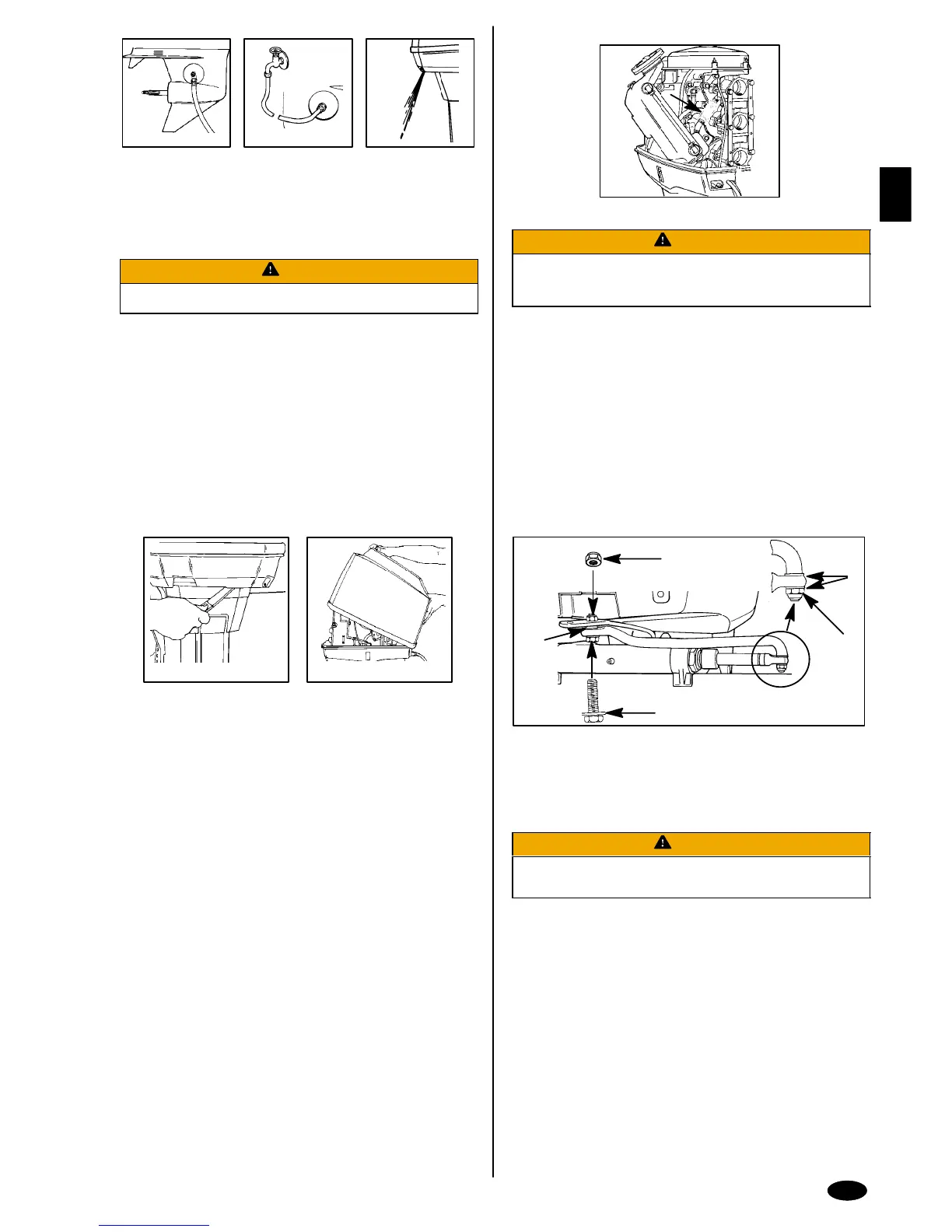
STEERING LINK ROD FASTENERS
IMPORTANT: The steering link rod that connects the steering cable to the
engine must be fastened using special washer head bolt (“a” - Part Number
10-90041) and self locking nylon insert locknuts (“b” & “c” - Part Number
11-34863). These locknuts must never be replaced with common nuts (non
locking) as they will work loose and vibrate off, freeing the link rod to
disengage.
WARNING
Disengagement of a steering link rod can result in the boat taking a full,
sudden, sharp turn. This potentially violent action can cause occupants
to be thrown overboard exposing them to serious injury or death.
Assemble steering link rod to steering cable with two flat washers (d) and nylon
insert locknut (“b” - Part Number 11-34863). Tighten locknut (b) until it seats, then
back nut off 1/4 turn.
Assemble steering link rod to engine with special washer head bolt (“a” - Part
Number 10-90041), locknut (“c” - Part Number 11-34863) and spacer (“e” -
12-71970). First torque bolt (a) to 20 lb. ft. (27 N·m), then torque locknut (c) to 20
lb. ft. (27 N·m).
 Loading...