STARTING SYSTEM
SERVICE MANUAL NUMBER 23
90-861326--1 MARCH 1999 Page 4A-47
6. If clearance is not within limits of .010-.160 in. (0.25-4.00 mm), it may indicate excessive
wear of solenoid linkage, shift lever yoke, or improper assembly of shift lever mecha-
nism. Replace worn or defective parts, since no provision is made for adjusting pinion
clearance.
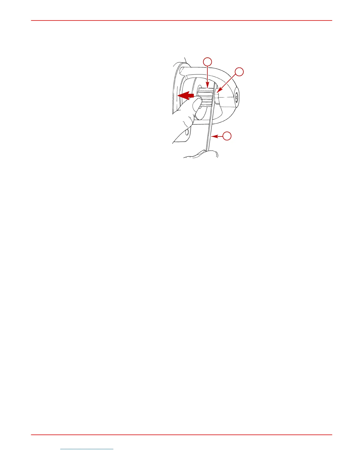
72077
a
b
c
a-Pinion
b-Retainer
c-Feeler Gauge
Installation
IMPORTANT: Install special mounting shim (if equipped) between starter motor and
engine block.
1. Place starter motor in position and install mounting bolts. Torque bolts to 30 lb-ft (41 Nm).
2. Connect YELLOW/RED wire to terminal S of solenoid. Connect ORANGE wire, RED
wire, and battery cable to large terminal of solenoid. Tighten fasteners securely. Coat
terminals with Quicksilver Liquid Neoprene. Install battery cable boot, if so equipped.
3. Connect battery cables to battery in the following order. Connect positive (+) cable to
positive (+) battery terminal and tighten cable clamp. Then connect negative (–) cable
to negative (–) terminal and tighten clamp.
Downloaded from https://needmanual.com/!
 Loading...

