EasyManua.ls Logo

Mercury OptiMax 250 Service Manual

Mercury OptiMax 250
39 pages
To Next Page IconTo Next Page
To Previous Page IconTo Previous Page
Page #12 background image
INSTALLATION
Page 1D-12 90-888438 JUNE 2002
Installing Jet Pump
Hull Cutout
CAUTION
The hull opening dimensions are critical for proper sealing between Jet Pump and
boat. Measure cutout thickness and overall dimensions before attempting a Jet
Pump installation.
1. Install tunnel grommet in cut-out of boat by gluing front portion of grommet to tunnel with
Loctite 454 or equivalent. Avoid gluing flexible sealing lips to tunnel.
ÀÀ
ÀÀ
ÀÀ
ÀÀ
ÀÀÀ
ÀÀ
CUTOUT THICKNESS
.375”
+0.050
–0.030
Use Grommet P/N:
25-877789
a
a
b
b
c
a-Glue Front Portion of Grommet
b-Avoid Gluing Flexible Sealing Lips to
Tunnel
c-Loctite 454
NOTE: The procedure for gluing the grommet is not required for the following grommets:
Part Number 820663–250 (1/4 in grommet)
Part Number 820663–375 (3/8 in grommet)
Part Number 882811 (3/8 in grommet)
2. Install steering and shift through hull bellows assemblies. Tighten securely.
a
b
c
d
a-Bellows
b-Clamp
c-Nut
d-Through Hull Fitting

Other manuals for Mercury OptiMax 250

Question and Answer IconNeed help?

Do you have a question about the Mercury OptiMax 250 and is the answer not in the manual?

Mercury OptiMax 250 Specifications

General IconGeneral
Engine TypeV6
Horsepower250 hp
Gear Ratio1.75:1
Starting SystemElectric Start
Alternator60 Amp
Shaft Length20", 25"

Summary

General Information

Notice to Installer

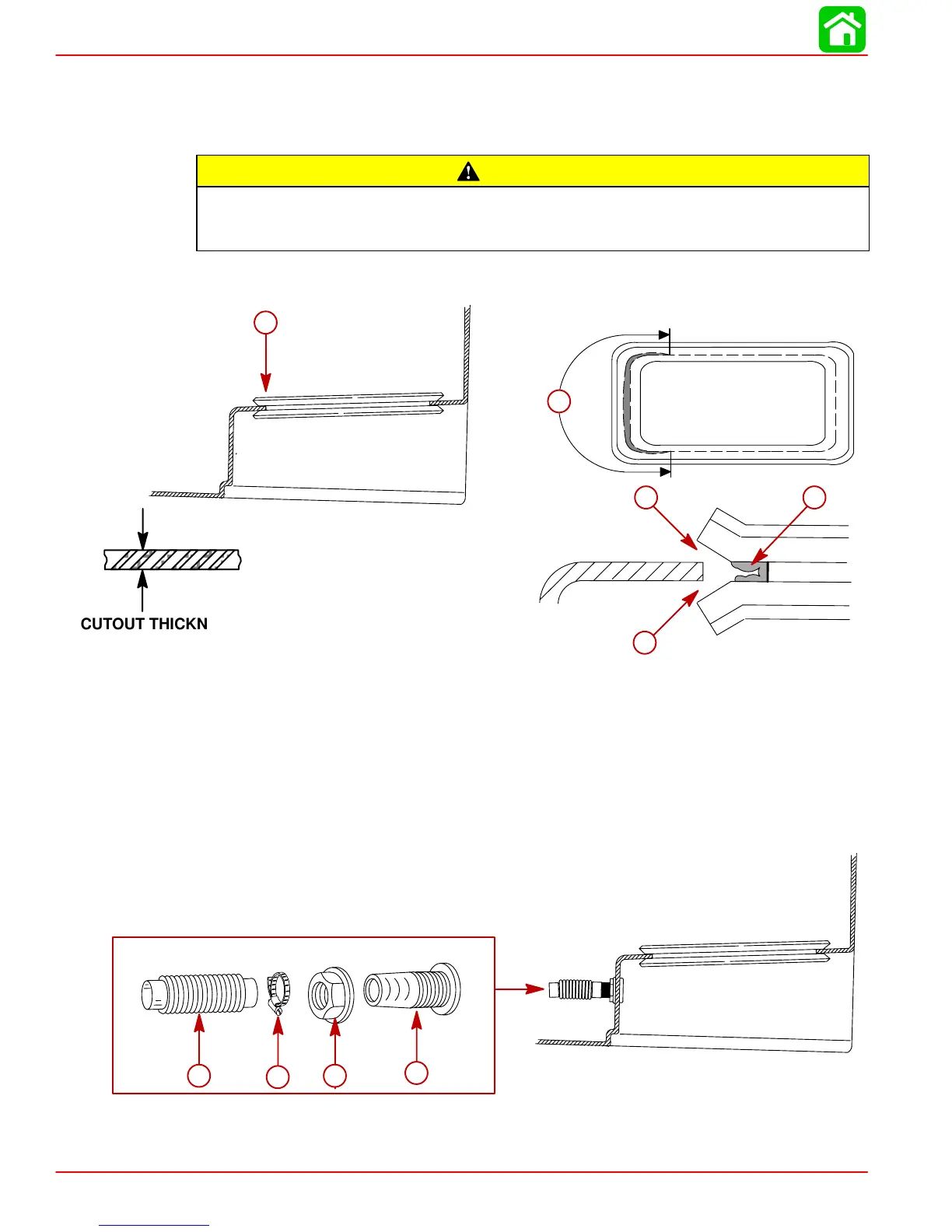
Alerts the installer to special instructions concerning operations that may be hazardous if performed incorrectly.

Torque Specifications

Installation Requirements

Battery/Battery Cables

Details battery selection criteria, cable sizing, and proper connection procedures.

Boat Construction

Engine Compartment Ventilation

Exhaust System

Fuel Delivery System

Instrumentation

Wiring Diagrams

SmartCraft System Monitor – Model Year 2001 and Newer

Remote Control and Cables

Mercury Jet Drive Hull Dimensions

Steering Helm and Cable

Installing Jet Pump

Hull Cutout

Provides critical dimensions for the hull opening and procedures for installing the tunnel grommet.

Steering Cable Adjustment

Shift Cable Adjustment

Bilge Siphon Feature

Installing Bilge Siphon

Instructions for installing the bilge siphon hose, break, and pick-up screen.

Water By-Pass System

Installation of Flushing Kit

Operation Instructions

Suggested Flushing Intervals

Installing Powerhead

Battery Connection

Throttle Cable Installation

Oil Injection Set-Up

Filling

Procedures for filling the remote oil tank and the engine oil tank.

Priming the Oil Injection Pump (If Required)

Explains how to check and reprime the oil injection pump using the Digital Diagnostic Terminal.

Purging Air From the Engine Oil Tank

Steps for purging air from the engine oil tank after filling to ensure proper oil flow.

Trim Plate Adjustment

Exhaust System Installation

General Exhaust System Notes

Covers standards, cautions, and requirements for marine exhaust system components and installation.

Exhaust Outlet Measurement Procedure

Procedure for measuring exhaust outlet location and checking exhaust system slope.

Pre-delivery Inspection

Related product manuals