INSTALLATION
Page 1D-4 90-888438 JUNE 2002
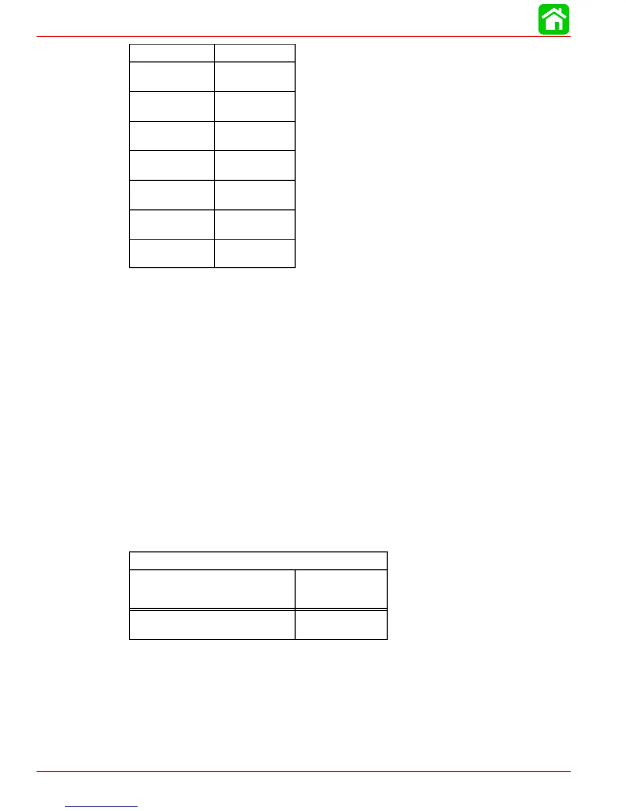
Cable Length Cable Gauge
Up to 3-1/2 ft.
(1.1 m)
4 (25mm
2
)
3-1/2 - 6 ft.
(1.1-1.8 m)
2 (35mm
2
)
6 - 7-1/2 ft.
(1.8-2.3 m)
1 (50mm
2
)
7-1/2 - 9-1/2 ft.
(2.3-2.9 m)
0 (50mm
2
)
9-1/2 - 12 ft.
(2.9-3.7 m)
00 (70mm
2
)
12 - 15 ft. (3.7-
4.6 m)
000 (95mm
2
)
15 - 19 ft. (4.6
- 5.8 m)
0000 (120mm
2
)
Boat Construction
IMPORTANT: All applicable U.S. Coast Guard regulations for INBOARD engines must
be complied with when constructing engine compartment.
Care must be exercised in the design and construction of the engine compartment. Seams
must be located so that any rain water or splash, which may leak through the seams, is di-
rected away from the engine and its air intake. Also, the passenger compartment drainage
system should not be routed directly to the engine compartment. Water that runs on or is
splashed in the air intake may enter the engine and cause serious damage to internal
engine parts.
IMPORTANT: Mercury Marine will not honor any warranty claim for engine damage
as a result of water entry.
Engine Compartment Ventilation
Engine compartment must be designed to provide a sufficient volume of air for engine
breathing and also must vent off any fumes in engine compartment in accordance with
industry standards (ABYC, NMMA, etc.), federal standards and U.S. Coast Guard regula-
tions for inboard engines. Pressure differential (outside engine compartment versus inside
engine compartment) should not exceed 2 in. (51mm) of water (measured with a manome-
ter) at maximum air flow rate.
Engine Compartment Specifications
Engine Air Requirements at Wide
Open Throttle
Physical Engine
Volume*
552 ft.
3
/min.
(0.260 m
3
/sec.)
1.41 ft.
3
(40.4 L)
* Physical engine volume is used in flotation calculations and is representative of the amount
of flotation the engine provides.
For serviceability, it is recommended that an additional 6 inches minimum (152 mm) (per
side) of clearance be allowed between powerhead and engine compartment walls.

 Loading...


