INSTALLATION
90-888438 JUNE 2002 Page 1D-5
Exhaust System
IMPORTANT: It is the responsibility of the boat manufacturer, or installing dealer, to
properly locate the engine. Improper installation may allow water to enter the expan-
sion chamber and combustion chambers and severely damage the engine. Damage
caused by water in the engine will not be covered by Mercury Marine Limited Warran-
ty, unless this damage is the result of defective part(s).
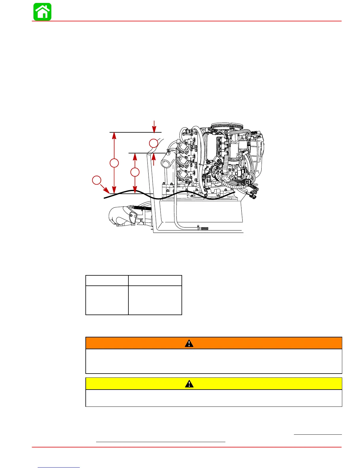
The engine must be properly located to ensure that water will not enter the engine through
the exhaust system. Determine the correct engine height by taking measurements (a) and
(b), with boat at rest in the water and maximum load aboard. Subtract (b) from (a) to find
(c). If (c) is less than specified in chart, boat construction must be altered to properly lower
waterline relative to exhaust chamber.
b
c
a
d
59216
a-From Waterline to Top of Transom
b-From Highest Point on Expansion Chamber to Top of Transom
c-(a) minus (b) = (c)
d-Waterline at Rest (at Maximum Load)
Model
c = (a) minus (b)
Jet Drive (c) must be 8 in.
(203 mm) or
more.
Fuel Delivery System
WARNING
Boating standards (NMMA, ABYC, etc.), federal standards and U. S. Coast Guard
regulations for INBOARD engines must be adhered to when installing fuel delivery
system. Failure to comply could result in severe personal injury or death.
CAUTION
Remove plastic plug from fuel inlet fitting. Attach fuel line to fuel fitting with U.S.
Coast Guard approved hose clamp. Inspect for fuel leaks.
1. Fuel pickup should be at least 1 in. (25 mm) from the bottom of the fuel tank to prevent
picking up impurities.
2. Fuel lines used must be U.S. Coast Guard approved (USCG type A1). Fittings and lines
must not be smaller than 5/16 in. (8 mm) I.D.

 Loading...


