67
APPENDIX D: FTR-120 FREE TOPOLOGY REPEATER
This chapter documents the FTR-120 Free Topology
Repeater and includes the following topics:
■ “About the FTR-120” on page 67
■ “Installing and Using the FTR-120” on page 67
ABOUT THE FTR-120
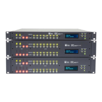
The FTR-120 is a four-channel network repeater. A message
generated on any network segment to which the FTR-120 is
connected is rebroadcasted on the three other channels.
There are six status LEDs on the unit:
■ The PWR LED is the power indicator. It is lit if power is
properly supplied to the unit.
■ The other five LEDs indicate the amount of network traf-
fic. The TX1-4 LED flashes when a message is transmit-
ted by the repeater. The RX1, RX2, RX3, RX4 LEDs flash
when a message is received on a particular channel.
For example, if a message is received on channel 1, the RX1
LED flashes, the message is transmitted on the other chan-
nels (2, 3, and 4), and the TX1-4 LED flashes.
NOTE: See Chapter 3, “Connecting RMS Net-
works” for configurations using the FTR-120
network repeater.
INSTALLING AND USING THE FTR-120
FTR-120 Physical Installation
The FTR-120 can be mounted on a wall or other surface
using four #6 wood screws (or equivalent). It can be
mounted horizontally with the terminal blocks facing down,
or vertically with the terminal blocks on the right side. The
FTR-120 unit and associated wiring should be mounted and
fastened securely, so that no stress is incurred. Do not install
the FTR-120 in a manner that would allow unanticipated dis-
connection.
FTR-120 Network Terminations
The FTR-120 is capable of providing standard network ter-
mination. As shipped, each channel on the unit has 5-ohm
network termination resistors connected. If no termination or
100-ohm network termination is required, the chassis lid
must be removed.
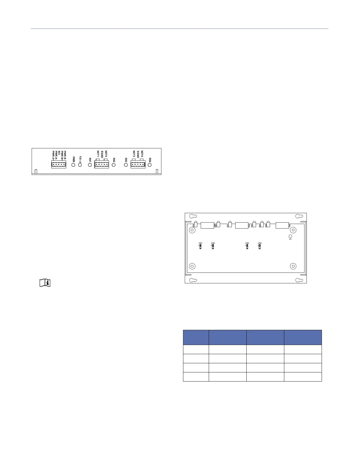
Network termination can be changed by moving the short-
ing jumper on CN1, CN2, CN3, or CN4. Table 4 describes
the jumper positions.
FTR-120 Free Topology Repeater
FTR-120 Jumper Layout
Table 4: FTR-120 Jumper Settings
Channel
Number
No
Termination
5-ohm
Termination
100-ohm
Term i nat i o n
CN1 No Jumper Jump 1 and 2 Jump 2 and 3
CN2 No Jumper Jump 1 and 2 Jump 2 and 3
CN3 No Jumper Jump 1 and 2 Jump 2 and 3
CN4 No Jumper Jump 1 and 2 Jump 2 and 3
 Loading...