Service Manual_2020-V1.0
20
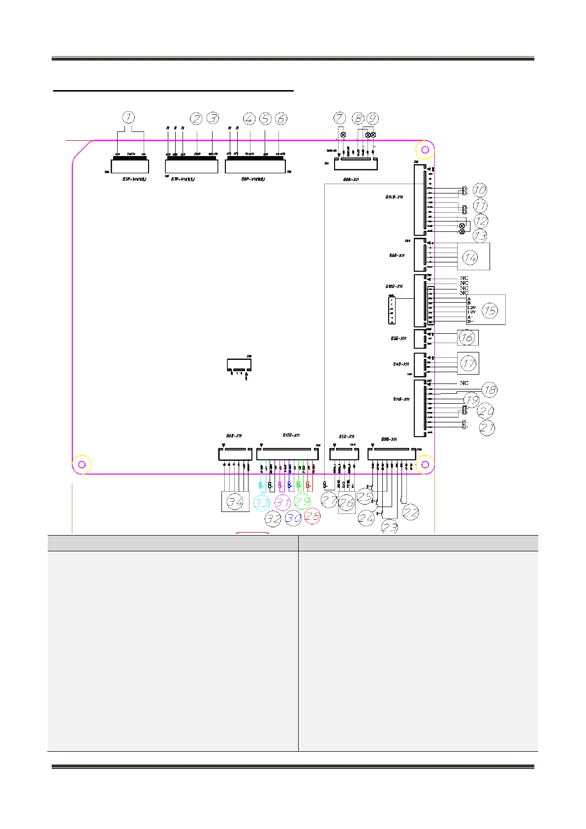
5.3 Main PCB terminal connection diagram
Name of Connecting terminals
Name of Connecting terminals
1. Power supply AC115V
2. Refrigeration compensation heater
3. Defrosting heater of refrigeration ice-making
compartment
4. Freezing defrost heater
5. Ice-making auxiliary defrosting heater
6. Flipping beam heating wire
7. Variable temperature anti-condensation heater
strip
8. Variable temperature lamp
9. Spotlight of freezing chamber
10. Fan of freezing chamber
11. Ice maker fan
18. Refrigeration water inlet heater strip
19. Freezing water inlet heater strip (Option)
20. Fan of refrigeration chamber
21. Condensate fan
22. Freezing door switch
23. Left refrigeration door switch
24. Right refrigeration door switch
25. Variable temperature door switch
26. Temperature and humidity sensor
27. Ice-making box bottom sensor
28. Freezing defrost sensor
29. Freezing sensor
30. Defrosting sensor of refrigeration ice-making
 Loading...