EasyManuals Logo
Home>Midea>Air Conditioner>V4+R Series

Midea V4+R Series User Manual

Midea V4+R Series
104 pages
To Next Page IconTo Next Page
To Previous Page IconTo Previous Page
Page #37 background imageLoading...
Page #37 background image
V4+R VRF 50/60Hz
201702 35
Part 3 - Control
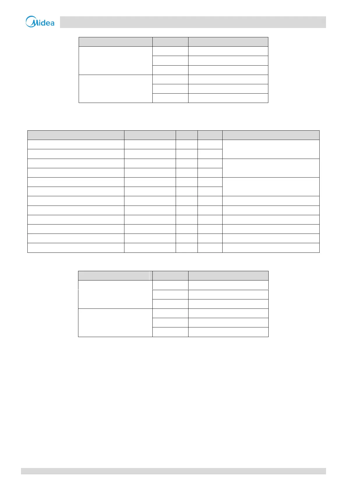
Table 3-7.2: Indoor unit component control during oil return operation in cooling mode
Component
Unit state
Control functions and states
Fan
Thermo on
Remote controller setting
Standby
Off
Thermo off
Off
Electronic expansion valve
Thermo on
Normal control
Standby
300 (steps)
Thermo off
300 (steps)
Tables 3-7.3 and 3-7.4 show component control during oil return operation in heating mode.
Table 3-7.3: Outdoor unit component control during oil return operation in heating mode
Component
Wiring diagram label
8-12HP
14-16HP
Control functions and states
Inverter compressor A
COMP(INV)
Controlled according to load requirement
Inverter compressor B
COMP(INV1)
DC fan motor A
FANA
Controlled according to discharge pressure
DC fan motor B
FANB
Electronic expansion valve A
EXVA
Fully open
Electronic expansion valve B
EXVB
Four-way valve
ST1
Off
Four-way valve
ST2
Off
Four-way valve
ST3
On
Solenoid valve (liquid refrigerant injection)
SV2
Normal control
Solenoid valve (oil balance)
SV4
Normal control
Solenoid valve (fast defrosting)
SV5
Off
Table 3-7.4: Indoor unit component control during oil return operation in heating mode
Component
Unit state
Control functions and states
Fan
Thermo on
Off
Standby
Off
Thermo off
Off
Electronic expansion valve
Thermo on
480 (steps)
Standby
480 (steps)
Thermo off
480 (steps)

Table of Contents

Questions and Answers:

Question and Answer IconNeed help?

Do you have a question about the Midea V4+R Series and is the answer not in the manual?

Midea V4+R Series Specifications

General IconGeneral
BrandMidea
ModelV4+R Series
CategoryAir Conditioner
LanguageEnglish

Related product manuals