V4+R VRF 50/60Hz
201608 87
Part 5 - Diagnosis and Troubleshooting
First troubleshooting step 4.19.5
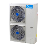
To troubleshoot xH4 errors, first ensure that the DC bus wire is connected correctly. The DC bus wire should run from the N
terminal on the inverter module, through the current sensor (in the direction indicated by the arrow on the current
sensor), and end at the N terminal on the DC filter board.
Figure 5-4.5: DC detection wire connection method
xL0 troubleshooting 4.19.6
Step 1: Check compressor
Check that compressor wiring is all connected properly.
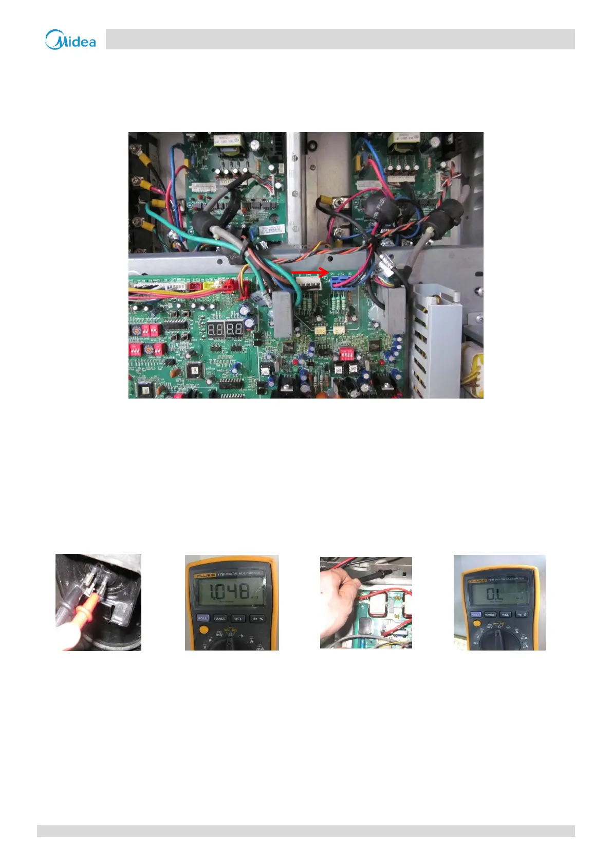
The normal resistances of the inverter compressor are 0.9-5Ω among U V W and infinite between each of U V W and
ground. If any of the resistances differ from these specifications, the compressor has malfunctioned.
Figure 5-4.6: Measuring resistances among compressor
terminals
Figure 5-4.7: Measuring resistances between compressor terminals
and ground
If the resistances are normal, go to Step 2.
Step 2: Check inverter module
The DC voltage between terminals P and N should be 1.41 times the local power supply voltage. The DC voltage
between terminals 1 and 2 should be 510-580V. If either voltage is not in the normal range, troubleshoot as for xL1 or
xL2 errors. Refer to Part 5, 4.19.7 “xL1/xL4 troubleshooting” or Part 5, 4.19.8 “xL2 troubleshooting”.
Disconnect the terminals 3, 4, 5 from the inverter compressor. Measure the resistance among terminals 1, 2, 3, 4, 5.
All the resistances should be infinite. If any of them are not infinite, the inverter module is damaged and should be
replaced.

 Loading...