V4+R VRF 50/60Hz
48 201608
Midea V4+R Series Service Manual
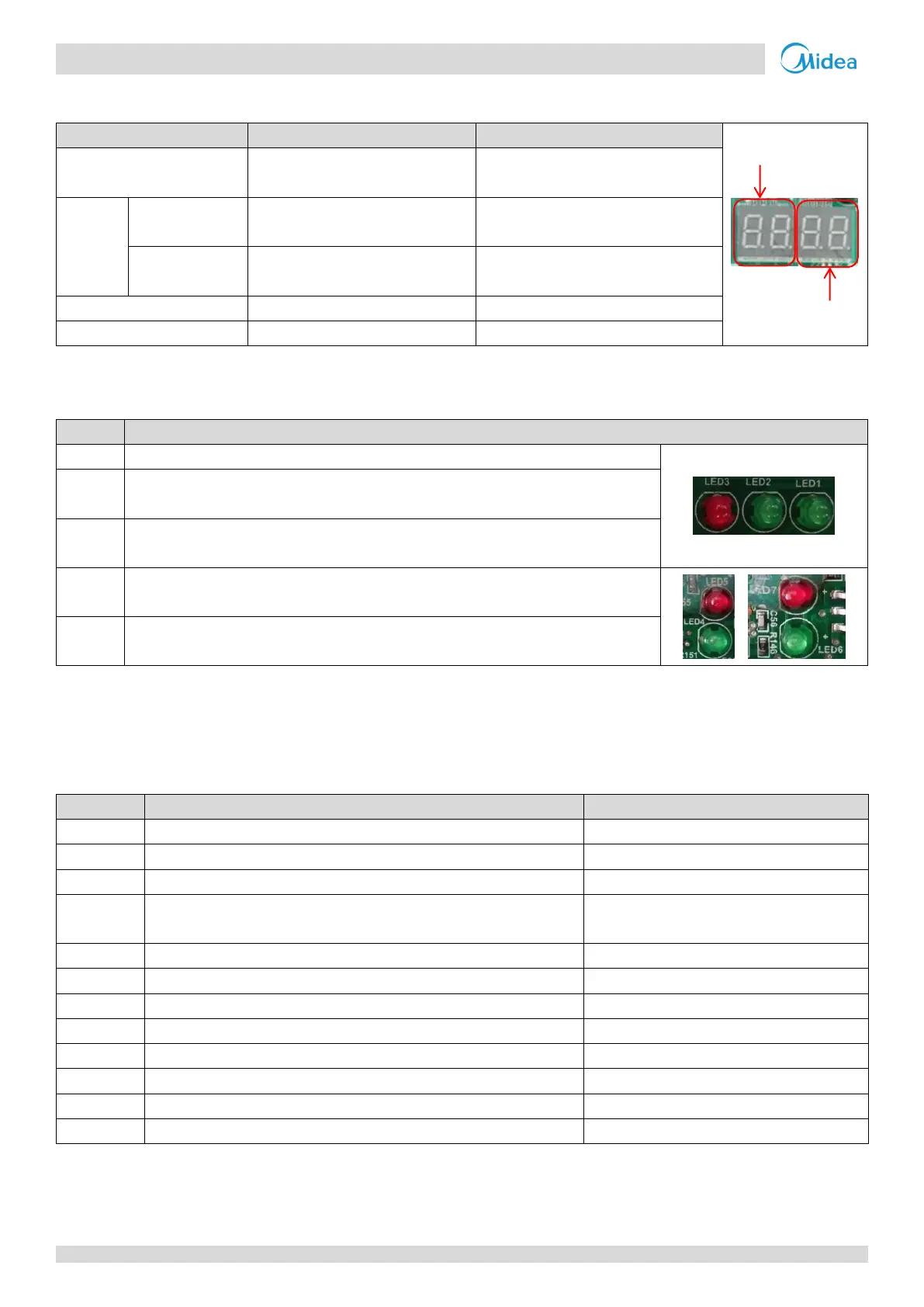
Digital display output 2.2.4
Table 5-2.4: Digital display output in different operating states
Parameters displayed on DSP1
Parameters displayed on DSP2
The number of indoor units in
communication with the outdoor units
For single
compressor units
Running speed of the compressor in
rotations per second
For dual
compressor units
Running speed of compressor B in
rotations per second
Running speed of compressor A in
rotations per second
LED indicators LED1 to LED7 2.2.5
Table 5-2.5: LED indicators LED1 to LED7
LED indicator function and status
Power supply indicator. Continuously on if the power supply is normal.
Running indicator. Continuously on if the system is operating normally and flashing if the
system has a problem.
Communication chip malfunction indicator. Flashing if a three-phase sequence protection
error or communication error has occurred.
Inverter module operating indicator. Continuously on if the compressor is running normally
and flashing if an inverter module error has occurred
1
.
Inverter module error indicator. Continuously on if an inverter module error has occurred
1
.
Notes:
1. If an inverter module error occurs, refer to Part 5, 4.19 “xH4 Troubleshooting”. The error code is displayed on the digital display.
3 Error Code Table
Table 5-3.1: Error code table
Communication error between outdoor units
Only displayed on the slave unit with the error
Displayed on the unit with the error
Communication error between indoor and master unit
Only displayed on the master unit
Outdoor ambient temperature sensor error and condenser pipe
temperature sensor error
Displayed on the unit with the error
Abnormal power supply voltage
Displayed on the unit with the error
Discharge pipe temperature sensor error
Displayed on the unit with the error
Outdoor unit address error
Displayed on the unit with the error
Displayed on the unit with the error
Communication error between main control chip and inverter driver chip
Displayed on the unit with the error
Communication error between main control chip and communication chip
Displayed on the unit with the error
Number of slave units detected by master unit has decreased
Only displayed on the master unit
Number of slave units detected by master unit has increased
Only displayed on the master unit
Notes:
1. 'x' is a placeholder for the compressor system (compressor and related electrical components), with 1 representing compressor system A and 2
representing compressor system B. 'y' is a placeholder for the address (1, 2 or 3) of the slave unit with the error.
Table continued on next page …

 Loading...