V4+R VRF 50/60Hz
88 201608
Midea V4+R Series Service Manual
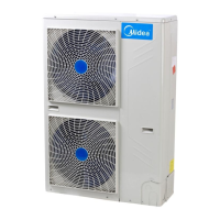
Figure 5-4.8: Inverter module terminals
xL1/xL4 troubleshooting 4.19.7
Step 1: Check inverter module
Check the DC voltage between terminals 1 and 2. The normal value is 510-580V. If the voltage is lower than 510V, go
to Step 2.
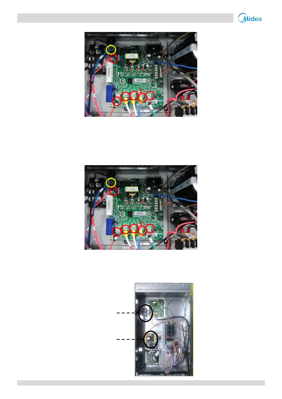
Figure 5-4.9: Inverter module terminals
Step 2: Check rectifier wiring circuit
If the wires are loose, fasten the wires. If the wires are OK, replace the main PCB.
Figure 5-4.10: Rectifier and AC filter board in electric control box
Check 3-phase bridge
rectifier wiring
Check AC filter
board wiring

 Loading...