V4+R VRF 50/60Hz
82 201608
Midea V4+R Series Service Manual
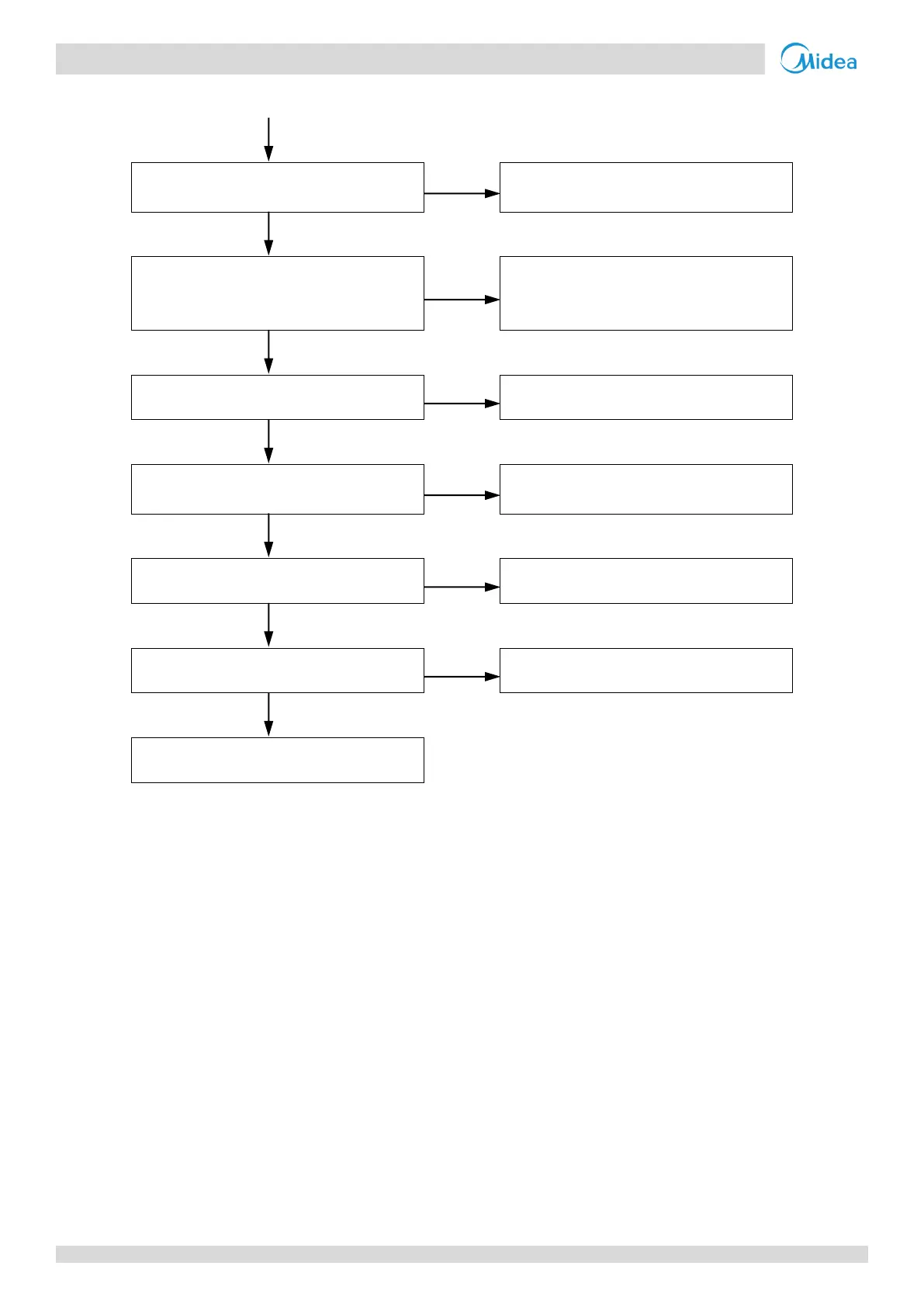
… flowchart continued from previous page
Discharge part of the refrigerant. Add oil
if it leaks during discharge
System contains air or nitrogen
3
Flush all refrigerant then vacuum the
system and recharge refrigerant. Add oil
to the system if it leaks
The condenser heat exchange is poor
4
Inspect the system and fix the error
The high pressure side is blocked, caused
by crushed or bent pipe or blocked EXV
5
Inspect the system and fix the error
Inverter module has short-circuited
6
Replace the inverter module
Compressor has malfunctioned
7
Notes:
1. An indoor load that is too large causes suction and discharge temperatures to be higher than normal. For normal system parameters refer to Tables 5-5.4
and 5-5.5 in Part 5, 5.2 “5.2 Normal Operating Parameters of Refrigerant System”.
2. To check for excess refrigerant:
Excess refrigerant causes discharge temperature to be lower than normal, discharge pressure to be higher than normal and suction pressure to be
higher than normal. For normal system parameters refer to Tables 5-5.4 and 5-5.5 in Part 5, 5.2 “5.2 Normal Operating Parameters of Refrigerant
System”.
3. Air or nitrogen in the system causes discharge temperature to be higher than normal, discharge pressure to be higher than normal, compressor current to
be higher than normal, abnormal compressor noise and an unsteady pressure meter reading. For normal system parameters refer to Tables 5-5.4 and 5-5.5
in Part 5, 5.2 “5.2 Normal Operating Parameters of Refrigerant System”.
4. In cooling mode check outdoor heat exchangers, fans and air outlets for dirt/blockages. In heating mode check indoor heat exchangers, fans and air outlets
for dirt/blockages.
5. High pressure side blockage causes discharge temperature to be higher than normal, discharge pressure to be higher than normal and suction pressure to
be lower than normal. For normal system parameters refer to Tables 5-5.4 and 5-5.5 in Part 5, 5.2 “5.2 Normal Operating Parameters of Refrigerant
System”.
6. Set a multi-meter to buzzer mode and test any two terminals of P N and U V W of the inverter module. If the buzzer sounds, the inverter module has
short-circuited. Refer to Figures 5-1.1 and 5-1.3 in Part 5, 1 “Outdoor Unit Electric Control Box Layout” and to Figure 5-4.1 in Part 5, 4.6 “E5
Troubleshooting”.
7. The normal resistances of the inverter compressor are 0.7-1.5Ω among U V W and infinite between each of U V W and ground. If any of the resistances
differ from these specifications, the compressor has malfunctioned. Refer to Figures 5-4.6 and 5-4.7 in Part 5, 4.19.6 “xL0 troubleshooting”.

 Loading...