Technical Information
31
VA
1
offee
stem
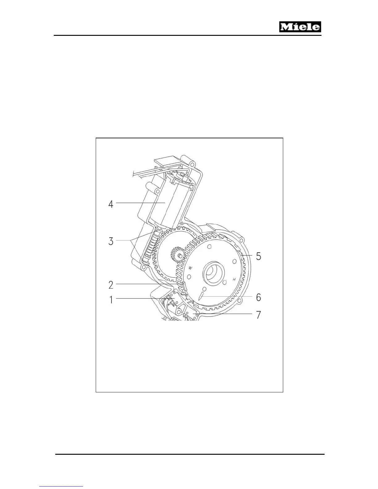
Refer to figure 5-18.
The Drive Motor (Item 4) powers the Worm Gear (Item 3). The drive
action is transferred to the Step-down Gear and then the Drive
Gear. The center of the Drive Gear contains the Drive Shaft that
connects to the Brew Unit Drive Shaft Socket. The drive gear The
drive shaft cog wheel has two switch actuators, (Items 2 & 5) for the
limit switches for the brew position and home position. The
electronic unit registers the brew position and the home position via
the limit switches, (Items 1 and 7).
1 Switch – home position switch
2 Switch actuator – home position
3 Bearing bush
4 Brew unit drive motor
5 Switch actuator – brew position
6 Fitting marking
7 Switch – brew position
Figure 4-18: Brew Unit Drive Assembly
 Loading...