3.2.3.2 Components and Structure
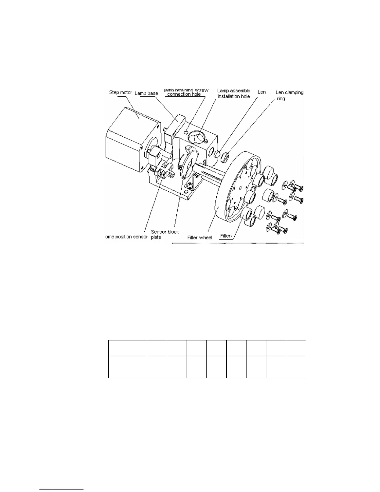
The assembly is composed of lamp base, filter wheel, step motor and etc. The
structure is shown as the following figure.
Figure 3-6 Lamp base assembly structure
3.2.3.3 Assembly and Disassembly of the Lamp Base Assembly
Lamp base assembly is fixed on the instrument base by 4 M4 socket head screws
and positioned by 2φ3 pins. When the assembly is dismounted as a whole, you can
disassemble the components, but you have to pay attention to the following
problems:
1 If fixture is not used when you assemble or disassemble the filter, extra care
should be taken lest the filter is scratched by the screw driver. Please follow the
correct order to install the filter. The order is shown in the following table.
No. 1 2 3 4 5 6 7 8
Wavelength
nm
340 405 546 670 450 510 578 630
450 nm and 670 nm are optional wavelengths. When these two wavelengths are
not configured, relevant position is shielded by stop plate; when relevant filters are
installed, the arrow on the circle should point outward of the hole.
2 When assembling or disassembling the home position sensor, place the surface
with text onward (refer to the base plate).
3 When assembling or disassembling the lens, make sure the spherical surface
face the outside. Press it until secure with clamping ring. Make sure that the
outer surface of the clamping ring is at the same level with or higher than the

 Loading...


