EasyManua.ls Logo

Mindray BA-88A Service Manual

Mindray BA-88A
79 pages
To Next Page IconTo Next Page
To Previous Page IconTo Previous Page
Page #45 background image
4 Hardware 4-
7
4.5.9 Detection of the Input Signal
Figure 4-10 Graph of input signal detection
The system should detect the signal from filter position sensor, aspirate button,
cuvette temp. controlling fan blocking. Before detected by control module, all input
signals should go through the level translation circuit.
4.5.10 Analogue Board Control
Figure 4-11 Graph of analogue board controlling
Three signals are controlled by analogue board: digital potentiometer control signal
(DCPx), channel selection signal (CH), AD collection and control signal (AD_Ox and
AD_lx). All control signals are generated by control module. The signals between the
control module end and analogue board should go through level translation (TTL to
LVTTL).
4.6 Analogue Board
The analogue board realizes the functions of photoelectric signal, temperature
sensor signal modulation and amplification, AD collection.
The photodiode transforms the light signal which has passed through the flow
cell (or cuvette) into voltage signal. The voltage signal will be filtered,
amplified inversely, and finally output at the outputting end of the AD
converter through selectable switch.

Table of Contents

Other manuals for Mindray BA-88A

Question and Answer IconNeed help?

Do you have a question about the Mindray BA-88A and is the answer not in the manual?

Mindray BA-88A Specifications

General IconGeneral
Light sourceHalogen lamp
Display7 inch touch screen
PrinterThermal printer
InterfaceRS232
Wavelengths340, 405, 546, 578, 630nm
Carry-over< 1%
Power SupplyAC 100~240V, 50/60Hz
Operating Temperature15-30°C

Summary

Foreword

Safety Symbols

Details the meaning and interpretation of various safety symbols used throughout the manual.

Safety Precautions

Preventing Electric Shock

Provides instructions to prevent electric shock, including warnings about opening covers and handling power.

Preventing Infection

Details necessary precautions to prevent biohazardous infection when handling samples.

Precautions on Use

Intended Use

Defines the system's intended application as an in vitro quantitative analyzer for clinical chemistries.

Operator

Specifies that the system must be operated by trained clinical professionals or authorized personnel.

Operating the System

Provides essential guidelines for operating the system safely and efficiently, including calibration and QC.

Maintaining the System

System Maintenance Procedures

Details standard maintenance procedures, including cleaning, power management, and part replacement guidance.

System Installation

Installation Procedures

Step-by-step guide for receiving, moving, connecting, powering on, and testing the analyzer.

Hardware

Safety Precautions for Hardware

Highlights crucial safety warnings when working with circuit boards, including ESD protection.

Connection of the Hardware System

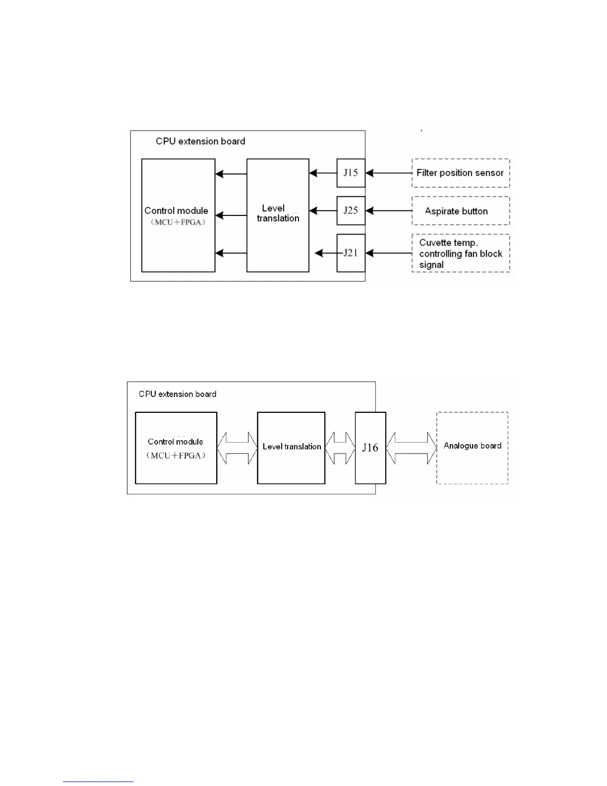
Illustrates the system's hardware connections and interfaces between various boards and external devices.

Service and Maintenance

Software Upgrading

Explains how to upgrade system software using a U disk, detailing procedures for CPU and extension boards.

Maintenance Procedures

Provides detailed procedures for replacing consumable parts like tubing and lamps, and for replacing CPU boards.

Troubleshooting

Alarm Message Classification

Categorizes error messages based on severity and explains how logs record error details.

Levels of Errors

Classifies system failures into three levels to facilitate troubleshooting and identify common corrective measures.

Error Details and Causes

Provides a comprehensive table detailing error codes, descriptions, causes, and corrective measures for various system failures.

Related product manuals