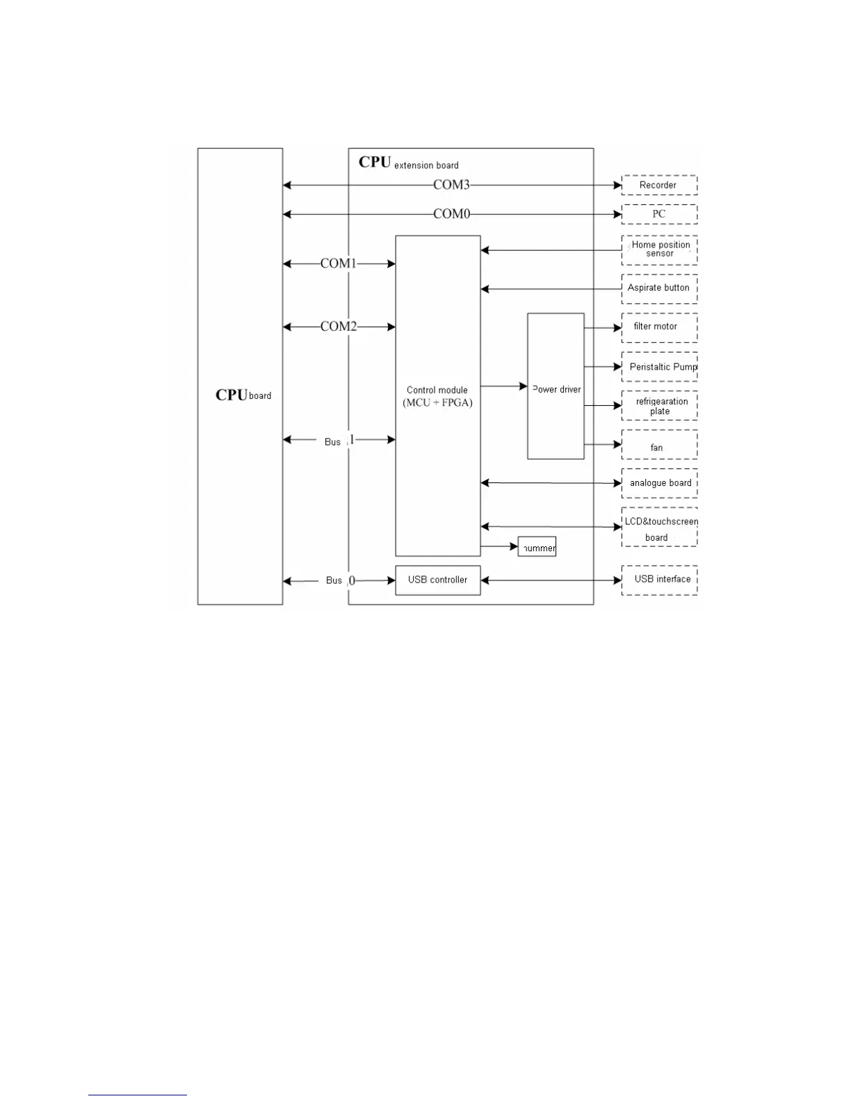
Figure 4-2 Structure of the CPU extension board
4.5.2 LED Indicator
D3: ++12V power indicator
D6: ++24V power indicator
D7: ++5.0V power indicator
D17: +3.3V power indicator
4.5.3 USB Functions
USB controller is configured on the CPU extension board which communicates with
the CPU via bus and realizes the USB communication function via USB interface.
USB power control and ESD protector is added between the USB controller and the
USB interface.

 Loading...


