Product Principle 4-15
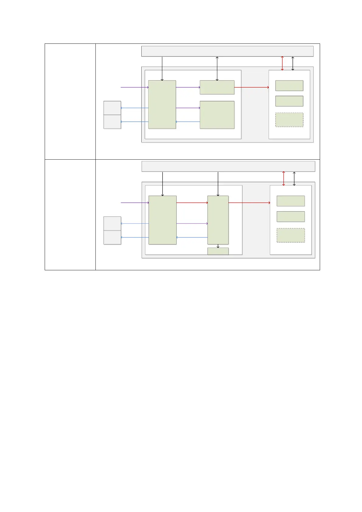
Figure 4-12 Schematic diagram of power unit
Configuration 1 is only set for power supply box (AC) before the 02.00.00(Rev 19070) (EGD019F)
version.
Configuration 1 and configuration 2 are set for power supply box (AC), in which the configuration 2
is the main part in and after 02.00.00(Rev 19070) (EGD019F) version.
Configuration 1: AC-DC module (with fan, 600W @ 12V), AC connection board, isolation
transformer.
Configuration 2: AC-DC board (300W @ 12V), without the AC connection board, no isolation
transformer, fan adapter board, independent fan.
4.5.1 AC-DC Module
AC-DC turns electric supply to direct current power supply.
AC input: the voltage is 200 to 240 Vac; 100 to 127 Vac, 50/60 Hz.
5VSTB output: standby power supply. It outputs to main control system when AC is in the
place.
12 V output: is controlled by main control system, non-standby power supply.
The signal when AC is in the place: reminds the validity of AC input. Main control system
goes into active standby via AC-DC module.
AC-DC Module
AC Interface
Module
Assistant Output
Module
DC-DC Module
AC input
Control System & Ultrasound Functions
AC output
AC output
Printer
DC supply
AC Unit
control
PHV Module
Battery
Assembly
DC Unit
power
Power Unit
Devices
control control
AC input
AC input
AC output
Control
Board
AC-DC Board
DC-DC Module
AC input
Control System & Ultrasound Functions
AC output
Printer
DC supply
AC Unit
control
PHV Module
Battery
Assembly
DC Unit
power
Power Unit
Devices
control control
DC supply
AC output
AC input
AC output
Fans

 Loading...


