Hardware Introduction
2-2
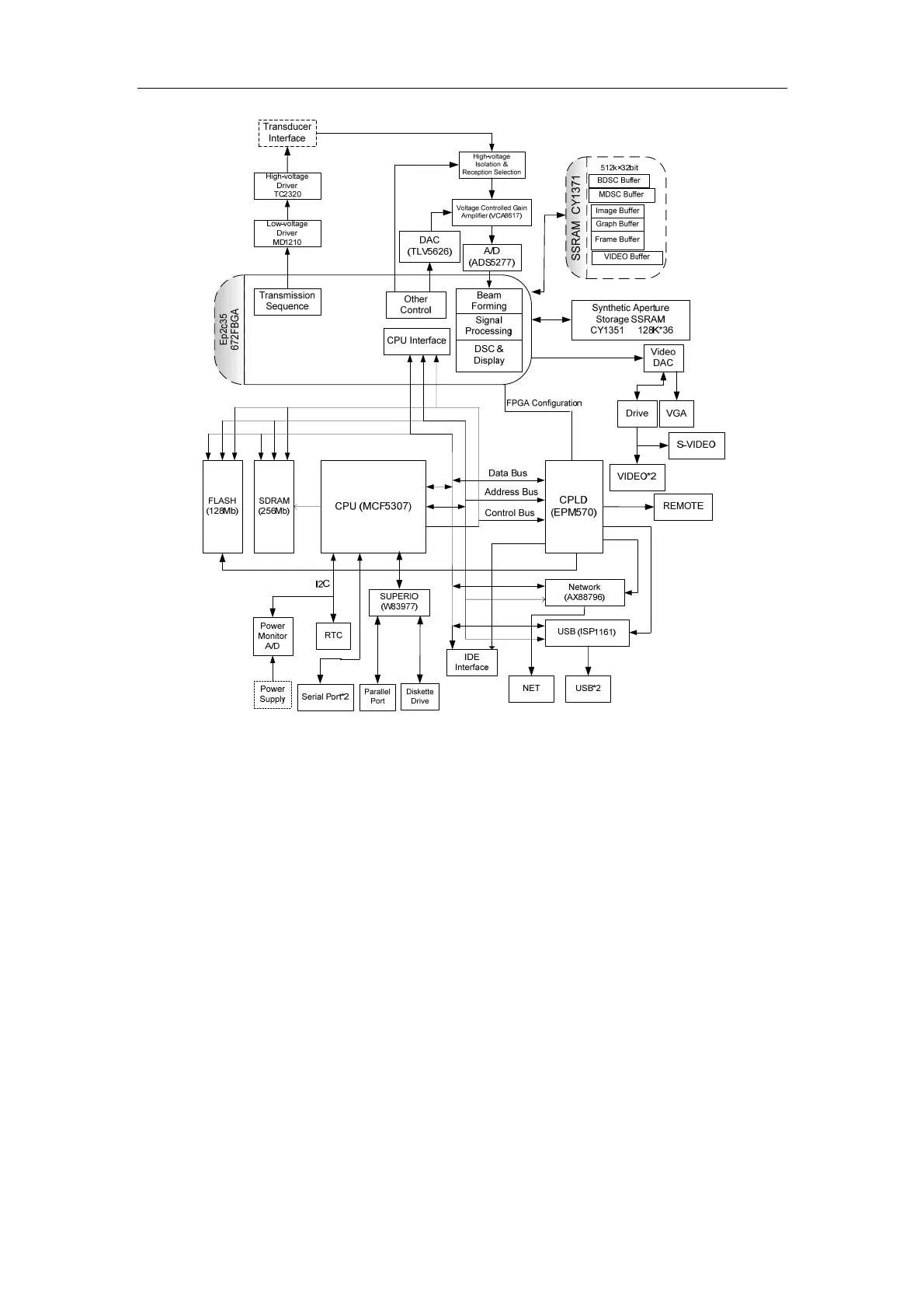
The front-end transmission circuit consists of MD1210 and TC2320. The reception circuit
includes ADG714, VCA8617 and ADS5277. The transmission sequence control and reception
channel selection are completed by FPGA.
The digital circuit consists of the CPU system and the FPGA system. The CPU system
includes CPU and the peripheral and interface circuit: FLASH, SDRAM, CPLD, power monitor
(ADT7462), reset circuit, clock circuit, real-time clock circuit (MAX6900), IDE interface, USB
interface, and Ethernet interface; The FPGA system includes FPGA, beam forming SSRAM,
DSC and display SSRAM, DAC conversion circuit and video interface; CPU is connected to
the peripheral and interface circuit with bus and also to FPGA with bus; The signal processing
is performed in FPGA.
2.2.2. Transducer Board
The diagram of the transducer board is shown as follows.
 Loading...


