Hardware Introduction
2-18
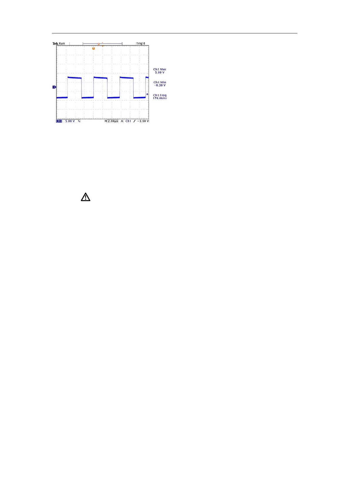
Voltage Waveform of U1.7
In the figure of GS Voltage Waveform of Q14, the duty ratio of drive waveform varies with the
AC input voltage. In the figure of DS Voltage Waveform of Q1, the amplitude of switch
waveform varies with the HV output. Besides the two waveforms describes before, the
amplitude, frequency and duty ratio of all waveforms tested during the service must be the
same with the figures above.
Warning: Take extreme caution when testing and
servicing boards to avoid damage of measurement
devices and boards and even body injury. Never touch any
parts on boards especially the primary circuit and the high
voltage part of secondary circuit.
2.4. Principle of the LCD
2.4.1. Operating Principle of the Inverter Module
The block diagram and functional diagram are shown in the following figures.
 Loading...


