Hardware Introduction
2-12
2.2.5. I/O Board
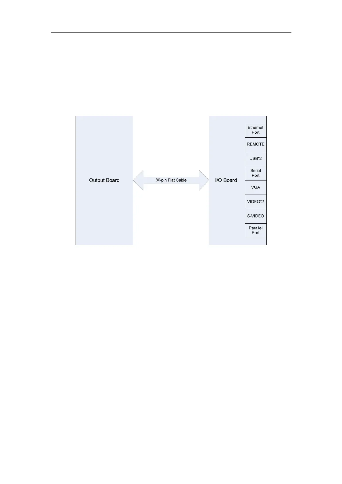
The I/O board, communicating with the output board through the 80-pin flat cable, provides
interfaces for all peripherals, such as the Ethernet port, serial port, parallel port, VGA,
REMOTE, S-VIDEO, USBs and VIDEOs. (Note: The I/O board of DP-8800 has no REMOTE
and only one VIDEO.)
The diagram of the I/O board is shown as follows.
2.3. Power Supply Board
2.3.1. Introduction
The power supply board provides +5V (D+5V and A+5V), +12V, +13.5V, +3.3V, -5V, +1.5V,
+2.5V and program-controlled high voltage for the system.
The connection board connects the power supply board, main board and transducer board,
filters output voltage, and performs the linear voltage-stabilizing from +3.3V to +3V and from
+1.5 to +1.2V. The filter circuit is π-type.
The diagram of the power supply board is shown as follows.
 Loading...


