2 Robot arm
Outside dimensions ・ Operating range diagram 2-16
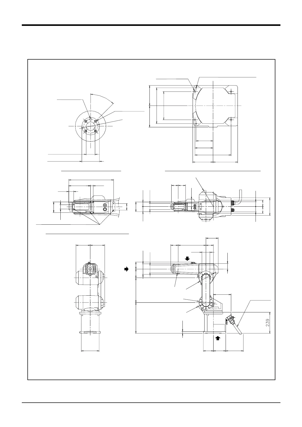
2.4 Outside dimensions ・ Operating range diagram
(1) RV-6SD/6SDC
Fig.2-3 : Outside dimensions : RV-6SD/6SDC
115
96
122
204
160
102.5
205
115 140
4-φ9 installation hole
2-φ6 holes
(prepared holes for φ8 positioning pins)
View D bottom view drawing : Detail of installation dimension
6.3a (Installation)
6.3a (Installation)
φ
3
1
.
5
4
5
°
φ20H7
+0.021
0
depth 8.5
φ40h8
-0.039
0
depth 6.5
φ5H7
+0.012
0
depth 9
View A: Detail of mechanical interface
4-M5 screw, depth 9
110
R
2
1
1
51.558.5
φ70
78
84
85
5461
78 73
200
80
37
32
340
20165
50
(for customer use)
View C: Detail of screw holes for fixing wiring hookup
Screw holes for fixing wiring hookup (M4)
162 165
204
A
B
200
115
140
φ
1
5
8
φ
1
5
8
R
9
8
80.5100
280
350
120
90
φ
5
3
20
85
85
315
140
90
63
200
* Dimensions when installing a solenoid valve (optional)
*
C
(Maintenance space)
Machine cable
*1)
*1) The depth in which the screw is tightened is 7.5 to 8.5mm.
 Loading...


